-
Notifications
You must be signed in to change notification settings - Fork 43
Development
ST-Link is not required, you can flash using DFU mode without any additional hardware.

| Option | Values | Description |
|---|---|---|
DFPLAYER |
NO/YES
|
Enable DFPlayer Voice support (Since 1.11.0+) |
FLYSKY_GIMBAL |
NO/YES
|
Enable FlySky FS-HZCZ03-ADJ gimbal support (Since 1.11.0+) |
PCBI6X_ELRS |
NO/YES
|
Enable ExpressLRS/CRSF configuration tool (LUA alternative) |
PCBI6X_INAV |
NO/YES
|
Enable INAV Lite radar screen |
PCBI6X_HELLO |
NO/YES
|
Example "Hello World" radio tool to help interested programmers to create their own |
USB_VBUS |
NO/YES
|
Enables detection of USB connection and removes main screen popup USB Connect option for USB_VBUS mod |
USB_SERIAL |
NO/YES
|
Enables USB Serial modes - Telemetry mirror or debug in DEBUG build. |
PCBI6X_BACKLIGHT_MOD |
NO/YES |
|
USB_MSD |
NO/YES
|
Enables USB Mass Storage mode. |
AFHDS2A_LQI_CH |
1-17 | Injects RSSI at channel, default: 17 |
CRSF_UNINVERTED |
NO/YES
|
Disable inversion of S.Port(CRSF), useful if you want to use ExpressLRS RX as TX option.(since 1.11.0+) |
CRSF_EXTENDED_TYPES |
NO/YES
|
Enable CRSF configuration parameters STRING and FLOAT types support. |
FAKE_RSSI |
NO/YES
|
Converts TRSS to RSSI data for receivers not sending RSSI. |
EXTPWR_INVERT |
NO/YES
|
Invert ext module power pin PC13 to allow use of P-MOSFET. (since 1.12.0+) |
PPM_UNIT |
US/PERCENT_PREC0/PERCENT_PREC1
|
Channel value unit |
DEBUG |
NO/YES
|
Enable DEBUG serial output |
GVARS |
NO/YES
|
Enable Global Variables |
HELI |
NO/YES
|
Enable Heli menu |
docker run --rm -it -e "BOARD_NAME=i6x" -e "CMAKE_FLAGS=PCB=I6X HELI=NO GVARS=YES PCBI6X_INAV=NO PCBI6X_ELRS=YES DEBUG=NO" -v ${PWD}:/opentx ajjjjjjjj/opentx-docker-i6x
Images to use:
ajjjjjjjj/opentx-docker-i6x - to compile using recent GCC version with LTO, this is current default.
vitass/opentx-fw-build - to compile older versions (1.8.0 and older) using GCC 4.7.
ST-Link: sudo st-flash write <file_to_flash>.bin 0x08000000
STM32 USB DFU Mode: dfu-util -a0 -s 0x08000000:leave -d 0483:df11 -D <file_to_flash>.bin
APM32 USB DFU Mode: dfu-util -a0 -s 0x08000000:leave -d 314b:0106 -D <file_to_flash>.bin
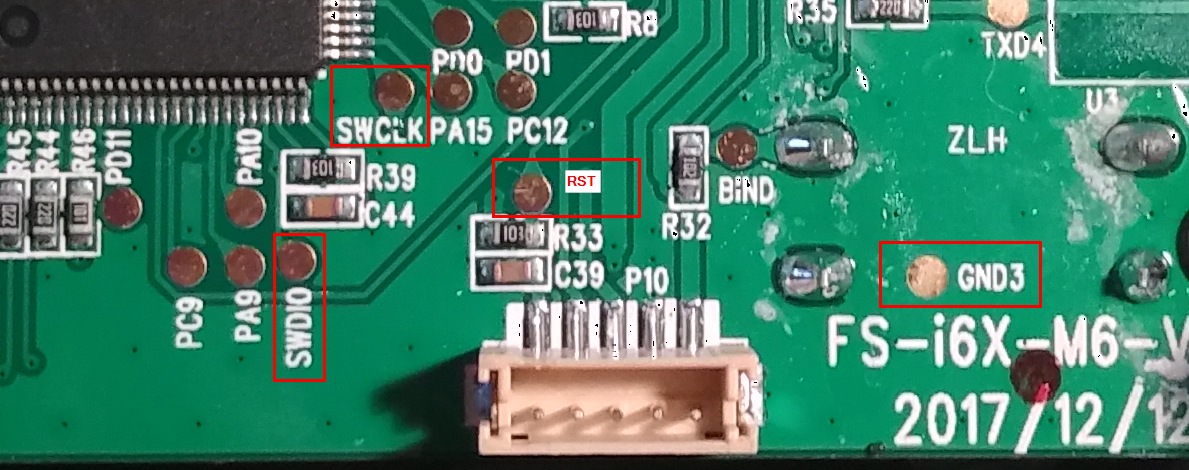
Use USB Serial mode for debug log or AUX Serial port TX located at PA9 PCB pad.
Serial port runs @115200 bauds, 8N1.
-------------------------------------
DMA
-------------------------------------

Channel 1: ADC              // ADC
Channel 2: TX1, TX3         // - not used - AUX Serial TX (USART1)
Channel 3: RX1, RX3         // AUX Serial RX (USART1)
Channel 4: TX1, TX2         // Telemetry TX DMA (TX2) (USART2), can be reused for A7105 SPI1 TX
Channel 5: RX1, RX2         // Telemetry RX DMA (TX2) (USART2), can be reused for A7105 SPI1 RX
Channel 6: RX2, RX3, RX4    // AUX4 Serial RX (USART4)
Channel 7: TX2, TX3, TX4    // - not used -

-------------------------------------
Exposed PADS
-------------------------------------

PA9     USART1_TX (AUX Serial TX)
PA10    USART1_RX (AUX Serial RX)

PB8     TIM16_CH1, I2C1_SCL
PB9     TIM17_CH1, I2C1_SDA

TX2 (PD5) USART2_TX (Telemetry)
PA15    USART2_RX, USB VBUS detection

PC9     TIM3_CH4 (Backlight PWM)
PC12    no useful AF
PC13    no AF, EXTMODULE Power switch
PC14    no AF, DFPLAYER BUSY
PC15    no AF.

PD0     SPI2_NSS, I2S2_WS, CAN_RX       // slave select
PD1     SPI2_SCK, I2S2_CK, CAN_TX       // clock
PD3     SPI2_MISO, I2S2_MCK, USART2_CTS // out
PD4     SPI2_MOSI, I2S2_SD, USART2_RTS  // in
PD11    no useful AF

PF9     TIM15_CH1 (PPM IN)
PF10    TIM15_CH2 (PPM OUT)

TXD4    USART3/4_TX (AUX3 Serial TX - DFPlayer)
RXD4    USART3/4_RX (AUX4 Serial RX - FS-HZCZ03-ADJ Gimbal)

-------------------------------------
Timers
-------------------------------------

TIM1    Buzzer PWM
TIM2    -
TIM3    BACKLIGHT_TIMER PWM
TIM6    STM32F0 delays
TIM7    TIMER_2MHz
TIM14   INTERRUPT_xMS
TIM15   PPM (External module) + Trainer
TIM16   Internal RF
TIM17   MIXER_SCHEDULER

-------------------------------------
NVIC priorities
-------------------------------------

Cortex-M0 have only 2-bits NVIC priorities: 0-3 instead of 0-15:
priority 6 becomes 2 (most probably OK),
priority 7 becomes 3 (OK),
priority 8 becomes 0 (wrong).
OpenI6X - Custom OpenTX / EdgeTX for FlySky i6X