Unike267 PRACTICES
- University: UPV/EHU.
- Master: Advanced Electronic Systems, SIEAV.
- Group: Digital Electronics Design Group, GDED (GIU21/007).
- Student: Unai Sainz-Estebanez.
This research has led to the publication of the following conference paper:
-
Published in: 2024 39th Conference on Design of Circuits and Integrated Systems (DCIS).
-
Date of Conference: 13-15 November 2024.
-
Conference Location: Catania, Italy.
-
Publisher: IEEE.
-
Co-authors:
- Unai Martinez-Corral (umarcor)
- Koldo Basterretxea
The aim of this repository is to perform a Characterization of hardware coprocessors integration with NEORV32 for the efficient implementation of SoCs based on RISC-V cores.
This characterization has been carried out in a VUnit simulation context and includes latency and throughput measurements of three different types of accelerators attached through four connection modes:
- Stream Link (AXI4-Stream)
- External Bus Interface (Wishbone)
- Custom Functions Unit (CFU)
- Custom Functions Subsystem (CFS)
The defining characteristics of the accelerators are as follows:
- Buffering not pipelined:
Mult_wfifos - Buffering pipelined:
Multp_wfifos - Not buffering:
Multp
In this way, the tests carried out are as follows:
| AXI-Stream (VC*) | AXI-Stream (Complex*) | Wishbone (VC) | WISHBONE (Complex) | CFU | CFS | |
|---|---|---|---|---|---|---|
| Buffering not pipelined | Latency/throughput | Latency/throughput | Latency/throughput | Latency/throughput | Latency | Latency/throughput |
| Buffering pipelined | Latency/throughput | Latency/throughput | Latency/throughput | Latency/throughput | Latency | Latency/throughput |
| Not buffering | Latency | Latency/throughput | Latency | Latency | Latency | Latency |
*VC: VUnit Verification Components
*Complex: NEORV32 + Accelerator
The following scheme shows the design of mult_wfifos accelerator:
To perform a transmission, each connection mode is associated with one or more CPU instructions. Is the running time involved in applying each of these instructions that will be measured through the control status register (CSR) mcycle performing four transmission for each test.
These instructions are principally lui, sw, add, addi, .word and are generated when the following C functions are compiled:
- Stream Link:
neorv32_slink_put(data)neorv32_slink_get()
- Wishbone:
neorv32_cpu_store_unsigned_word(address,data)neorv32_cpu_load_unsigned_word(address)
- CFU
neorv32_cfu_r3_instr(funct7, funct3, rs1, rs2)
- CFS
NEORV32_CFS->REG[C] = out_datain_data = NEORV32_CFS->REG[C]
In this context, the methodology followed to realize the measurements has been generalized for all tests writing the functions that generate the instructions to be measured between csr_write(mcycle,zero) and csr_read(mcycle).
As shown in the following C code:
neorv32_cpu_csr_write(CSR_MCYCLE, 0);
//Functions that generate the instructions to be measured
neorv32_cpu_csr_read(CSR_MCYCLE);
Then, the value of the CSR(mcycle) has been extracted in simulation through the VUnit info() function adding the following code to the test bench:
mycycle_capture: process
  begin
    done <= false;
    wait until start and rising_edge(clk);
    for x in 0 to test_items-1 loop
      wait until rising_edge(clk) and csr_we = '0' and csr_valid = '1' and
      csr_addr = x"B00" and csr_rdata_o /= x"00000000"; -- CSR MYCYCLE ADDR IS 0xB00
      info(logger, "Data " & to_string(x+1) & "/" & to_string(test_items) & " latency is " &
      to_string(to_integer(unsigned(csr_rdata_o))-1) & " cycles");
      wait until rising_edge(clk);
    end loop;

    wait until rising_edge(clk);
    done <= true;
    wait;
  end process;
Thus, we will have automated the latency/throughput measurement every time the simulation of the Complex is launched visualizing the results of the measurements at the end of the simulation.
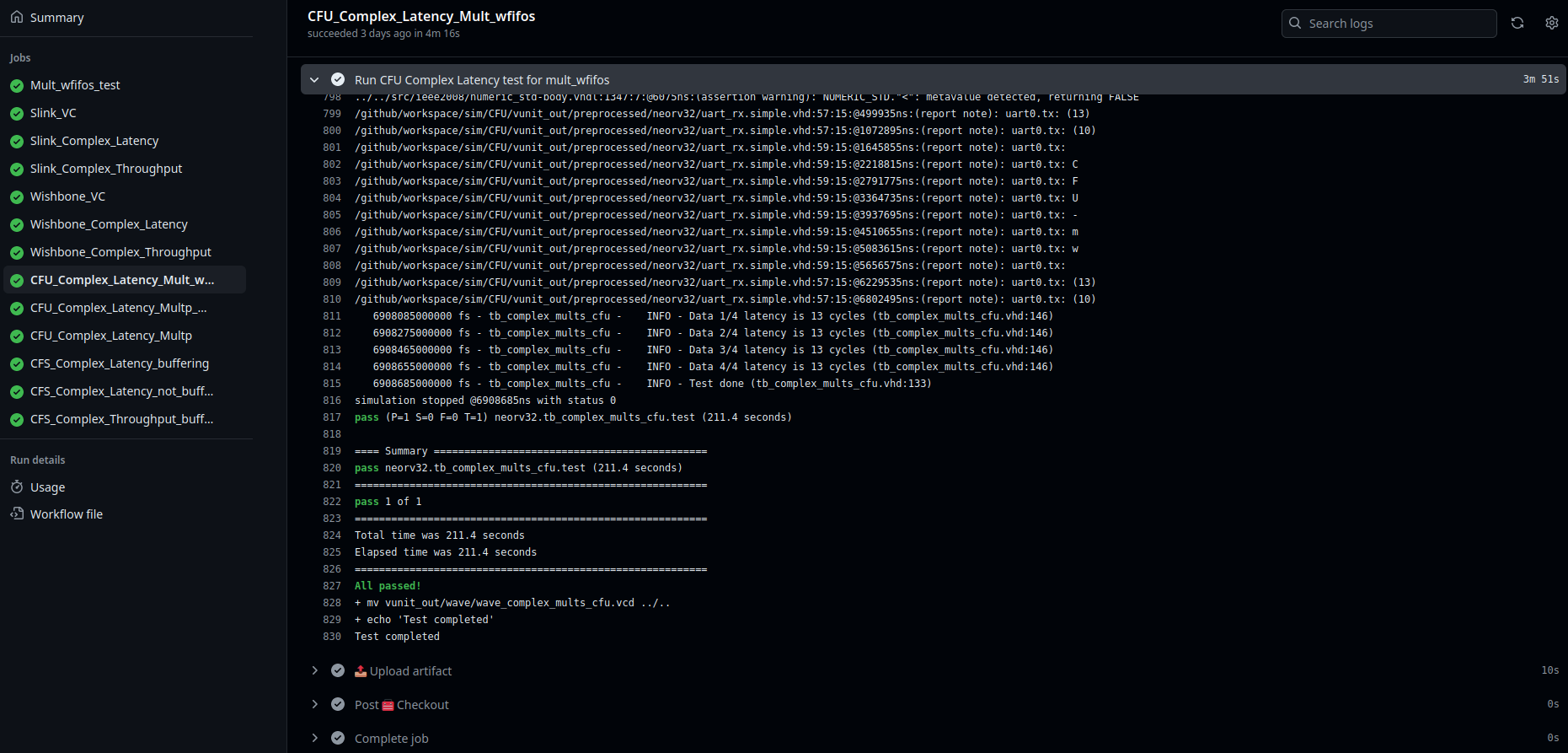
These results can be consulted in the github actions associated with the continuous integration of the simulation.
The following image exemplifies this process for the mult_wfifos CFU Complex Latency test, but would be analogous for all tests.
The latency and throughput measurement results are summarized in the following tables:
| Latency | AXI-Stream (VC) | AXI-Stream (Complex) | Wishbone (VC) | WISHBONE (Complex) | CFU | CFS |
|---|---|---|---|---|---|---|
| Buffering not pipelined | 6 | 45 | 5 | 16 | 13 | 37 |
| Buffering pipelined | 4 | 45 | 3 | 16 | 11 | 37 |
| Not buffering | 1 | 45 | 2 | 16 | 8 | 18 |
These results are in system clock cycles. CPU clock period is 10 ns (100 MHz).
| Throughput | AXI-Stream (VC) | AXI-Stream (Complex) | Wishbone (VC) | WISHBONE (Complex) | CFU | CFS |
|---|---|---|---|---|---|---|
| Buffering not pipelined | 1/4 | 1/20 | 1/2 | 1/5 | X | 1/15 |
| Buffering pipelined | 1 | 1/20 | 1/2 | 1/5 | X | 1/15 |
| Not buffering | X | 1/20 | X | X | X | X |
These results are in data per system clock cycle. CPU clock period is 10 ns (100 MHz).
The entire design implementation workflow, including simulation, synthesis, place and root and generate/load bitstream are fully supported through FOSS tools.
This implementation has been successfully performed on the Arty A7 35t and Arty A7 100t FPGAs for all accelerators using the following container.
This container is built and pushed in continuous integration in the following repository and contains GHDL, yosys, nextpnr-xilinx and prjxray.
Additionally, the complete workflow has also been implemented using the proprietary software Vivado.
All the bitstreams are available in the github actions associated with the continuous integration of the implementation.
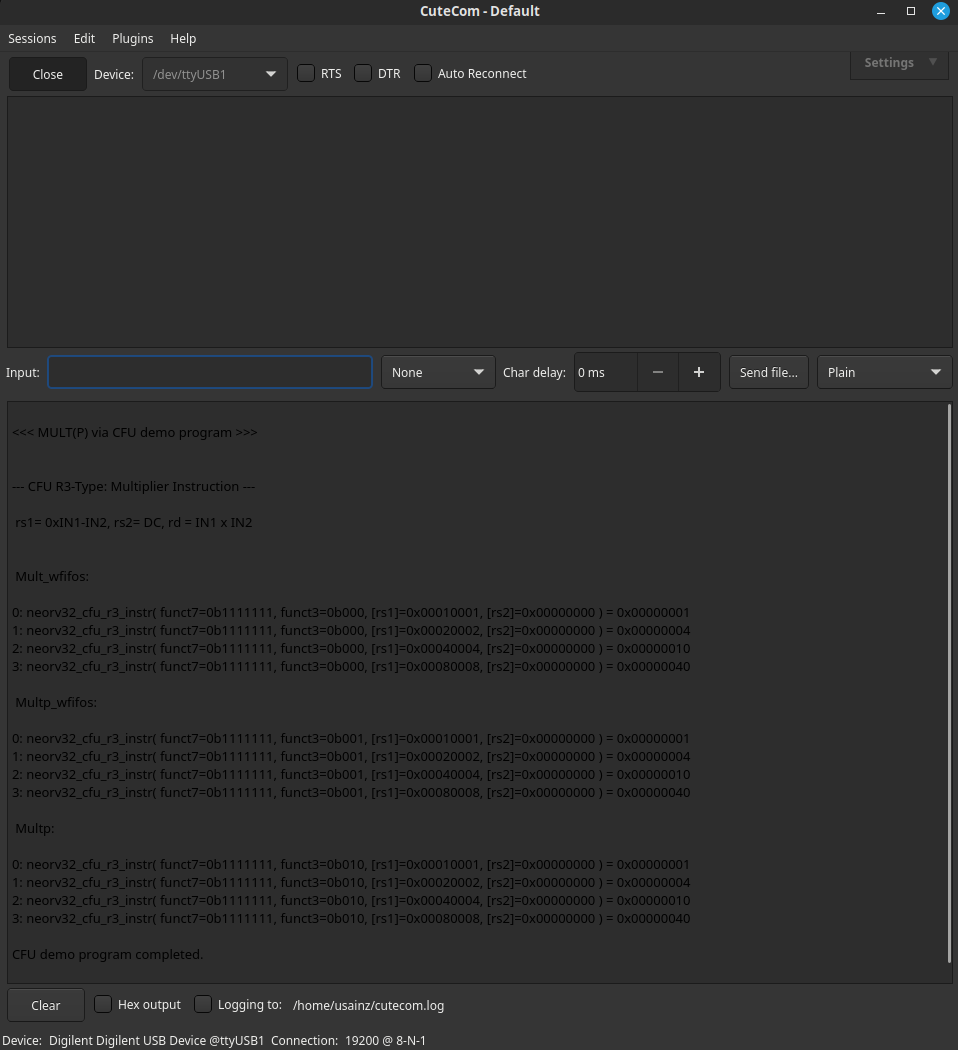
The following image shows the results for CFU implementation visualized through CuteCom terminal:


