You signed in with another tab or window. Reload to refresh your session.You signed out in another tab or window. Reload to refresh your session.You switched accounts on another tab or window. Reload to refresh your session.Dismiss alert
GDSII, short for Graphic Design System, is a data format used for the exchange of integrated circuit or layout data in Electronic Design Automation (EDA). GDSII is a binary file format that presents planar geometric shapes, text labels, and related layout information in a hierarchical manner. Over the past 30 years, GDSII has become a standard, with almost all EDA software and hardware systems supporting it.
In the 1980s, GDSII was developed as a standard by Calma. Over the years however, ownership has been passed from Calma to GE, then to Valid, and finally to Cadence. Although versions of GDSII have gone through iterative updates, the format and syntax of it have basically remained unchanged. GDSII has consistently served as the industry-standard database for integrated circuit layouts. Despite significant developments in OASIS, GDSII still remains the primary format for describing the physical layout of chips. To a degree, the long lifespan of GDSII can be attributed to its elegant architecture and simplicity. Additionally, the slow adoption of alternative solutions, like OASIS, may be impacted by the presence of the vast legacy codebase.
This article provides examples to help readers quickly understand the GDSII format, and how to read and write GDS files.
GDSII Format
The GDSII file format is clear and straightforward, defining the file's library, structure, and various parameters through keywords. This article focuses on what one may encounter when working on CAD/CAE/EDA projects.
Library records
The GDSII file always begins with the HEADER record, which includes the version number being used. Next, the BGNLIB record documents the date of the last modification and last access to the file. LIBNAME details the library's name. Following this are optional file header records: REFLIBS, FONTS, ATTRTABLE, GENERATIONS, and FORMAT. The final record in the file header must be UNITS, which documents units and precision. After the file header, there is the structure section. When all the information is defined, the file concludes with the ENDLIB record.
Each structure has two header records and one tail record, enclosing an arbitrary list of elements. The first structure header record is BGNSTR, which includes the creation date and last modification date. Following this is the STRNAME record. Then, the structure section is open, listing of one of seven elements: BOUNDARY, PATH, SREF, AREF, TEXT, NODE, BOX. The final record for a structure is ENDSTR. Following it must be another structure section or the conclusion of the entire library, ENDLIB.
BGNSTR
STRNAME
...
ENDSTR
Boundary Element
The boundary element defines a filled polygon. It begins with the BOUNDARY record and may include optional the records ELFLAGS and PLEX. Following these, it must include the LAYER, DATATYPE, and XY records. The LAYER record is used to specify the layer for this boundary (numbered from 0 to 63). The DATATYPE record contains insignificant information, and its parameter should be zero. The XY record includes a variable number of coordinate pairs, ranging from 4 to 200 pairs, to define the outline of the polygon. The number of points in the record is determined by how long the record is. It's important to note that since the boundary must be closed, the first and last coordinate values must be the same.
A path is an open graphic with a non-zero width. It's typically used for placing conductor wires. It begins with the PATH record, followed by optional ELFLAGS and PLEX records. Next, the LAYER record must be included to specify the desired path material. Additionally, a DATATYPE record and an XY record must be present to define the path's coordinates. A path can include anywhere from 2 to 200 points. Before the XY record is applied for path specification, there are two optional records: PATHTYPE and WIDTH. The PATHTYPE record describes the nature of the endpoints of the path segment. If its value is 0, the segment will have square endpoints terminating at the path vertices. A value of 1 indicates round endpoints, and a value of 2 indicates square endpoints with a width equal to half their width. The width of the path is defined by the optional WIDTH record. If the width value is negative, it will scale independently of any structure.
The SREF record represents a structure reference, allowing structures to be referenced within other structures, thereby achieving hierarchy. Following this are optional ELFLAGS and PLEX records. Next, the SNAME documents the name of the structure required, and the XY record contains a single coordinate to place this structure. Before the XY record, there may be optional transformation records. If structure transformation is needed, the STRANS record will appear first.
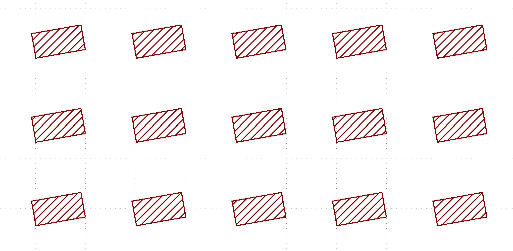
In addition to the SREF used for individual structures, GDSII also has the AREF (array reference) element, which can place one-dimensional or two-dimensional structure arrays. This is useful for particularly integrated circuit layouts, including memory. After the optional ELFLAGS and PLEX records, there is the SNAME record to specify the structure being arrayed. Following this, the optional transformation records; STRANS, MAG, and ANGLE, provide the orientation of instances. Then, the COLROW record msut appear to specify the number of columns and rows in the array. The final record is an XY record, which contains three points: the coordinates of the origin instance, the coordinates of the last instance in the column direction, and the coordinates of the last instance in the row direction.
Text can be included in a circuit using the TEXT record. It starts with the TEXT keyword, followed by optional ELFLAGS and PLEX records. Next is the required LAYER record. Then, a TEXTTYPE record with zero parameters will appear. The optional PRESENTATION record specifies the font. Optional PATHTYPE, WIDTH, STRANS, MAG, and ANGLE records can adjust the text. The last two records are mandatory: an XY record with a single coordinate to position the text, and a STRING record to express the actual text.
TEXT
LAYER 0
TEXTTYPE 2
PRESENTATION 0
XY 5000: 3000
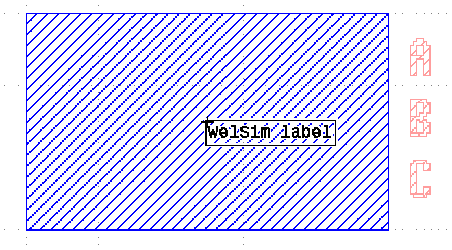
STRING WelSim label
ENDEL
Node Element
The NODE record can specify circuit information. The information in this element is not graphical and does not affect the manufactured circuit. Instead, its intended use is for other CAD systems that utilize topological information. Further details are beyond the scope of this article.
The last element in a GDSII file is the BOX element. After the BOX record, there may be optional ELFLAGS and PLEX records. Then, followed by the required LAYER record. It also includes a BOXTYPE record with zero parameters and an XY record. The XY record must contain five points describing a closed rectangle. Unlike a boundary, this is not a filled graphic. Therefore, it is not used to describe the geometric shape of an integrated circuit.
In addition to commercial software vendors, there are many free GDSII tools available. These free tools include editors, viewers, utilities for converting 2D layout data into a generic 3D format, utilities for converting binary formats to readable ASCII formats, and libraries. Through testing and use, we have found:
KLayout is an open-source circuit layout visualization and editing tool. It's user-friendly and suitable for beginners. The open-source code is also suitable for in-depth learning. It supports the conversion of binary GDS files to human-readable ASCII text.
gdstk is an open-source GDS I/O library based on C++ with a friendly interface, making it suitable for use in commercial GDS-related projects. There is also a Python version available.
Developing custom applications related to GDSII is not complex. It can be combined with other CAD kernel modules and 2D/3D display modules to achieve more advanced functionality.
Conclusion
GDSII is a simple syntax two-dimensional CAD file format, commonly used in integrated circuit and chip design. The GDS ecosystem is rich, with extensive support from both commercial and open-source software, making it user and developer-friendly. If you are developing EDA/CAE software, the knowledge of supporting GDSII files may be necessary.
WelSim is not affiliated with GDSII, OASIS, Cadence, KLayout, or gdstk. The development team and organization behind GDSII, OASIS, Cadence, KLayout, and gdstk have no connection to WelSim. This reference is used here solely for the purpose of a technical blog article and software usage.
reacted with thumbs up emoji reacted with thumbs down emoji reacted with laugh emoji reacted with hooray emoji reacted with confused emoji reacted with heart emoji reacted with rocket emoji reacted with eyes emoji
-
GDSII, short for Graphic Design System, is a data format used for the exchange of integrated circuit or layout data in Electronic Design Automation (EDA). GDSII is a binary file format that presents planar geometric shapes, text labels, and related layout information in a hierarchical manner. Over the past 30 years, GDSII has become a standard, with almost all EDA software and hardware systems supporting it.
In the 1980s, GDSII was developed as a standard by Calma. Over the years however, ownership has been passed from Calma to GE, then to Valid, and finally to Cadence. Although versions of GDSII have gone through iterative updates, the format and syntax of it have basically remained unchanged. GDSII has consistently served as the industry-standard database for integrated circuit layouts. Despite significant developments in OASIS, GDSII still remains the primary format for describing the physical layout of chips. To a degree, the long lifespan of GDSII can be attributed to its elegant architecture and simplicity. Additionally, the slow adoption of alternative solutions, like OASIS, may be impacted by the presence of the vast legacy codebase.
This article provides examples to help readers quickly understand the GDSII format, and how to read and write GDS files.

GDSII Format
The GDSII file format is clear and straightforward, defining the file's library, structure, and various parameters through keywords. This article focuses on what one may encounter when working on CAD/CAE/EDA projects.
Library records
The GDSII file always begins with the HEADER record, which includes the version number being used. Next, the BGNLIB record documents the date of the last modification and last access to the file. LIBNAME details the library's name. Following this are optional file header records: REFLIBS, FONTS, ATTRTABLE, GENERATIONS, and FORMAT. The final record in the file header must be UNITS, which documents units and precision. After the file header, there is the structure section. When all the information is defined, the file concludes with the ENDLIB record.
Structure records
Each structure has two header records and one tail record, enclosing an arbitrary list of elements. The first structure header record is BGNSTR, which includes the creation date and last modification date. Following this is the STRNAME record. Then, the structure section is open, listing of one of seven elements: BOUNDARY, PATH, SREF, AREF, TEXT, NODE, BOX. The final record for a structure is ENDSTR. Following it must be another structure section or the conclusion of the entire library, ENDLIB.
Boundary Element
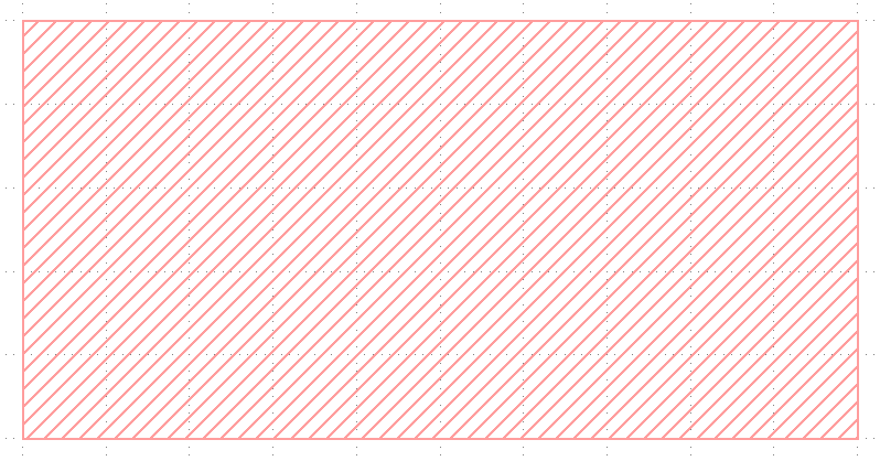
The boundary element defines a filled polygon. It begins with the BOUNDARY record and may include optional the records ELFLAGS and PLEX. Following these, it must include the LAYER, DATATYPE, and XY records. The LAYER record is used to specify the layer for this boundary (numbered from 0 to 63). The DATATYPE record contains insignificant information, and its parameter should be zero. The XY record includes a variable number of coordinate pairs, ranging from 4 to 200 pairs, to define the outline of the polygon. The number of points in the record is determined by how long the record is. It's important to note that since the boundary must be closed, the first and last coordinate values must be the same.
Path Element
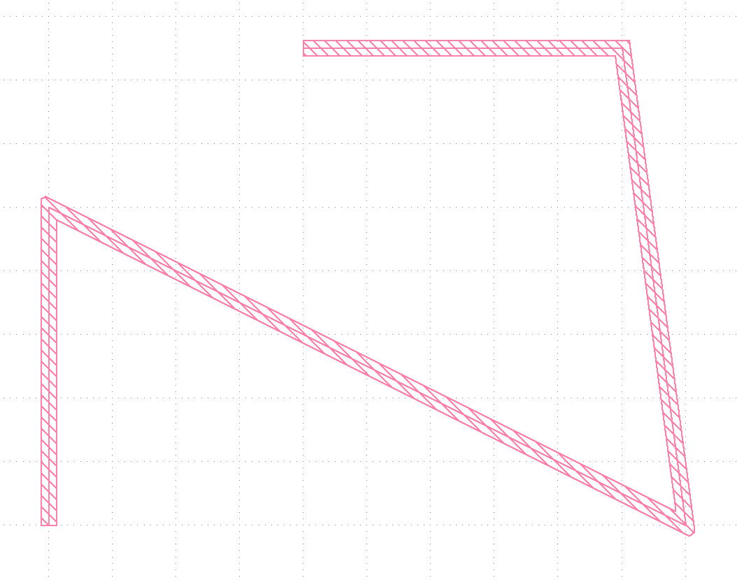
A path is an open graphic with a non-zero width. It's typically used for placing conductor wires. It begins with the PATH record, followed by optional ELFLAGS and PLEX records. Next, the LAYER record must be included to specify the desired path material. Additionally, a DATATYPE record and an XY record must be present to define the path's coordinates. A path can include anywhere from 2 to 200 points. Before the XY record is applied for path specification, there are two optional records: PATHTYPE and WIDTH. The PATHTYPE record describes the nature of the endpoints of the path segment. If its value is 0, the segment will have square endpoints terminating at the path vertices. A value of 1 indicates round endpoints, and a value of 2 indicates square endpoints with a width equal to half their width. The width of the path is defined by the optional WIDTH record. If the width value is negative, it will scale independently of any structure.
SREF Element
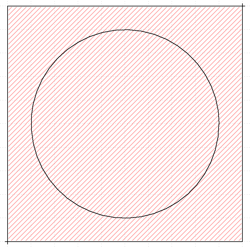
The SREF record represents a structure reference, allowing structures to be referenced within other structures, thereby achieving hierarchy. Following this are optional ELFLAGS and PLEX records. Next, the SNAME documents the name of the structure required, and the XY record contains a single coordinate to place this structure. Before the XY record, there may be optional transformation records. If structure transformation is needed, the STRANS record will appear first.
AREF Element
In addition to the SREF used for individual structures, GDSII also has the AREF (array reference) element, which can place one-dimensional or two-dimensional structure arrays. This is useful for particularly integrated circuit layouts, including memory. After the optional ELFLAGS and PLEX records, there is the SNAME record to specify the structure being arrayed. Following this, the optional transformation records; STRANS, MAG, and ANGLE, provide the orientation of instances. Then, the COLROW record msut appear to specify the number of columns and rows in the array. The final record is an XY record, which contains three points: the coordinates of the origin instance, the coordinates of the last instance in the column direction, and the coordinates of the last instance in the row direction.
Text Element
Text can be included in a circuit using the TEXT record. It starts with the TEXT keyword, followed by optional ELFLAGS and PLEX records. Next is the required LAYER record. Then, a TEXTTYPE record with zero parameters will appear. The optional PRESENTATION record specifies the font. Optional PATHTYPE, WIDTH, STRANS, MAG, and ANGLE records can adjust the text. The last two records are mandatory: an XY record with a single coordinate to position the text, and a STRING record to express the actual text.
Node Element
The NODE record can specify circuit information. The information in this element is not graphical and does not affect the manufactured circuit. Instead, its intended use is for other CAD systems that utilize topological information. Further details are beyond the scope of this article.
Box Element
The last element in a GDSII file is the BOX element. After the BOX record, there may be optional ELFLAGS and PLEX records. Then, followed by the required LAYER record. It also includes a BOXTYPE record with zero parameters and an XY record. The XY record must contain five points describing a closed rectangle. Unlike a boundary, this is not a filled graphic. Therefore, it is not used to describe the geometric shape of an integrated circuit.

Reading and Writing GDS Files
In addition to commercial software vendors, there are many free GDSII tools available. These free tools include editors, viewers, utilities for converting 2D layout data into a generic 3D format, utilities for converting binary formats to readable ASCII formats, and libraries. Through testing and use, we have found:
Conclusion
GDSII is a simple syntax two-dimensional CAD file format, commonly used in integrated circuit and chip design. The GDS ecosystem is rich, with extensive support from both commercial and open-source software, making it user and developer-friendly. If you are developing EDA/CAE software, the knowledge of supporting GDSII files may be necessary.
WelSim is not affiliated with GDSII, OASIS, Cadence, KLayout, or gdstk. The development team and organization behind GDSII, OASIS, Cadence, KLayout, and gdstk have no connection to WelSim. This reference is used here solely for the purpose of a technical blog article and software usage.
Beta Was this translation helpful? Give feedback.
All reactions