You signed in with another tab or window. Reload to refresh your session.You signed out in another tab or window. Reload to refresh your session.You switched accounts on another tab or window. Reload to refresh your session.Dismiss alert
In three-dimensional CAE simulation analysis, it is often necessary to select interior surfaces of geometric bodies or choose surfaces that are occluded. This is applicable when setting up contact conditions for complex assemblies in structural analysis, defining boundary conditions for inner surfaces in electromagnetic, fluid, or thermal analyses, among other scenarios. Such requirements pose significant demands on the pre-processing modules of engineering simulation software.
Currently, a common approach in the industry is to add a selection layer view in a small region within the 3D graphics window. This feature displays the selection layers after clicking on a geometric body, enabling the user to modify the desired surfaces. This method is simple, intuitive, and provides a good user experience. However, this service adds extra software development work, as it requires incorporating an additional viewport in the 3D window. When implementing a selection layer view, the impact the feature has on the overall software performance must also be paid attention to.
Selection layer view
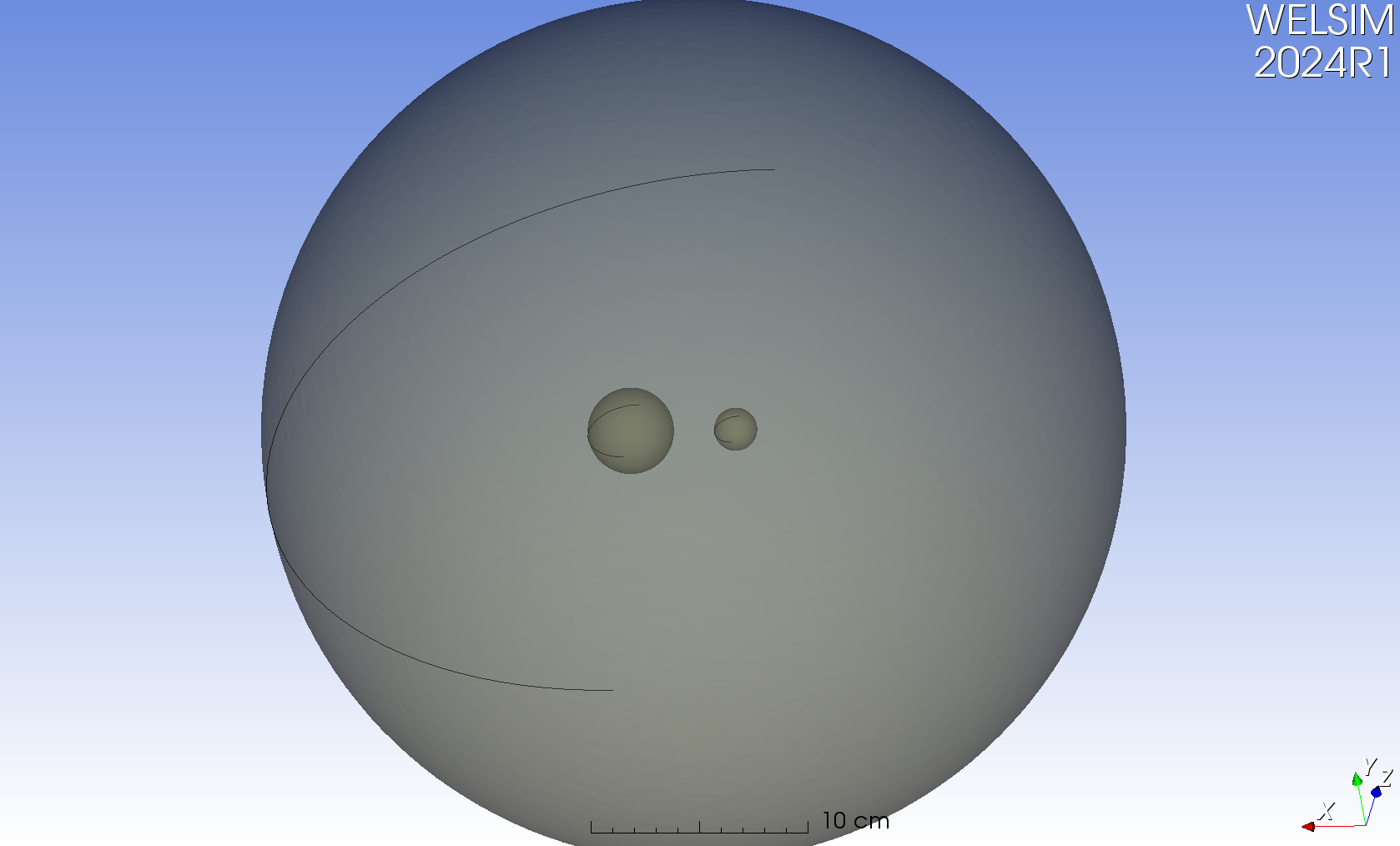
In the model below, there is a sphere with two small spherical cavities inside. When the model is set to be semi-transparent, the positions and sizes of the internal cavities can be observed. In 3D electromagnetic analysis, the exterior surface is often set as the far-field boundary, and various excitations are applied to the inner surface, such as voltage. Similarly, in fluid and thermal analysis, certain boundary conditions are set for the inner surface. In such cases, the GUI operation needs to be able to select the interior surfaces of the sphere.
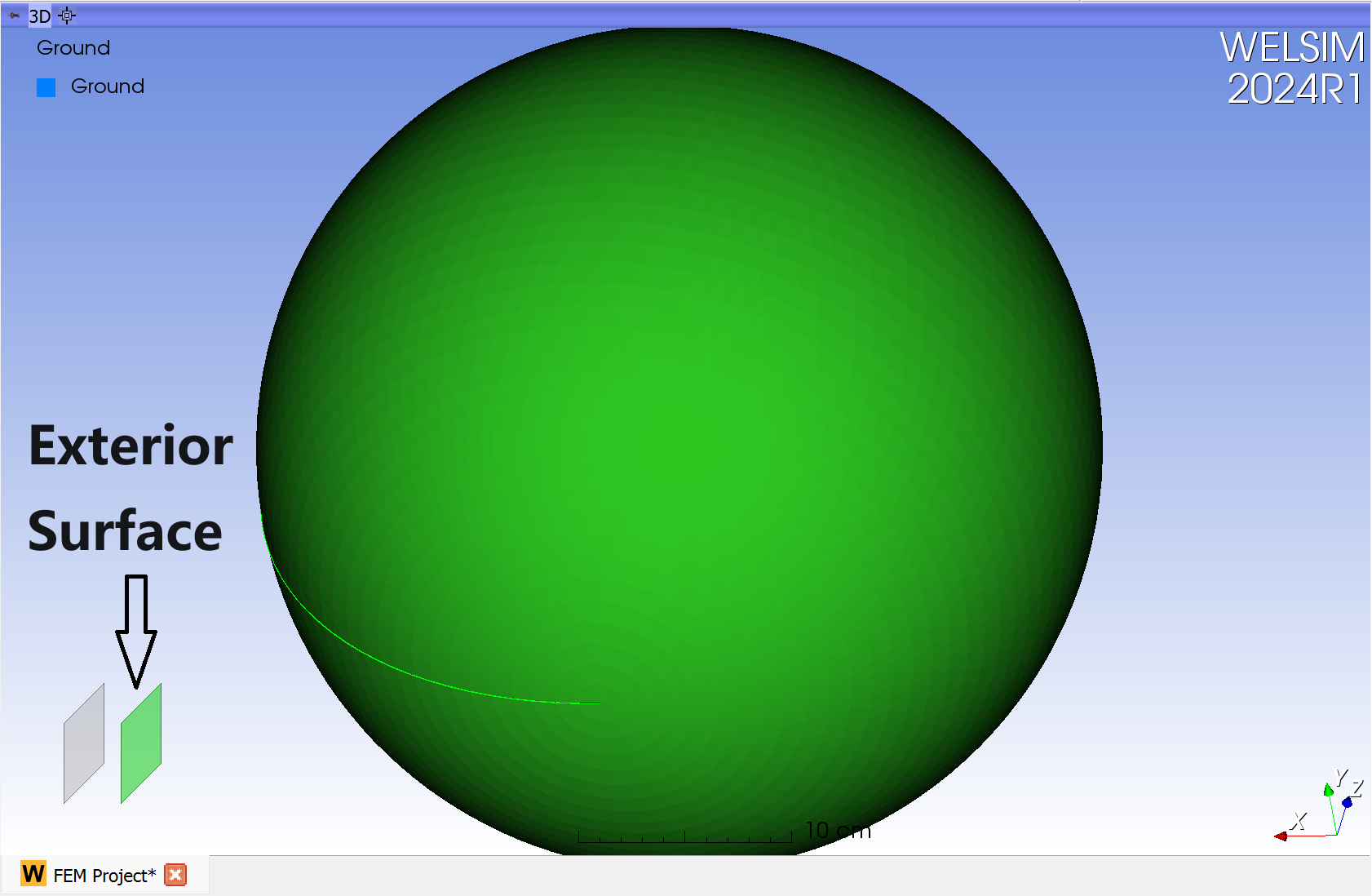
When clicking on the position of the internal spherical cavity, the default outermost surface is selected and highlighted in green. If there are more optional surfaces, the layer view will be displayed. At this point, the layer view shows two layers: the unselected inner surface on the left, represented in gray; the selected outer surface on the right, highlighted in green.
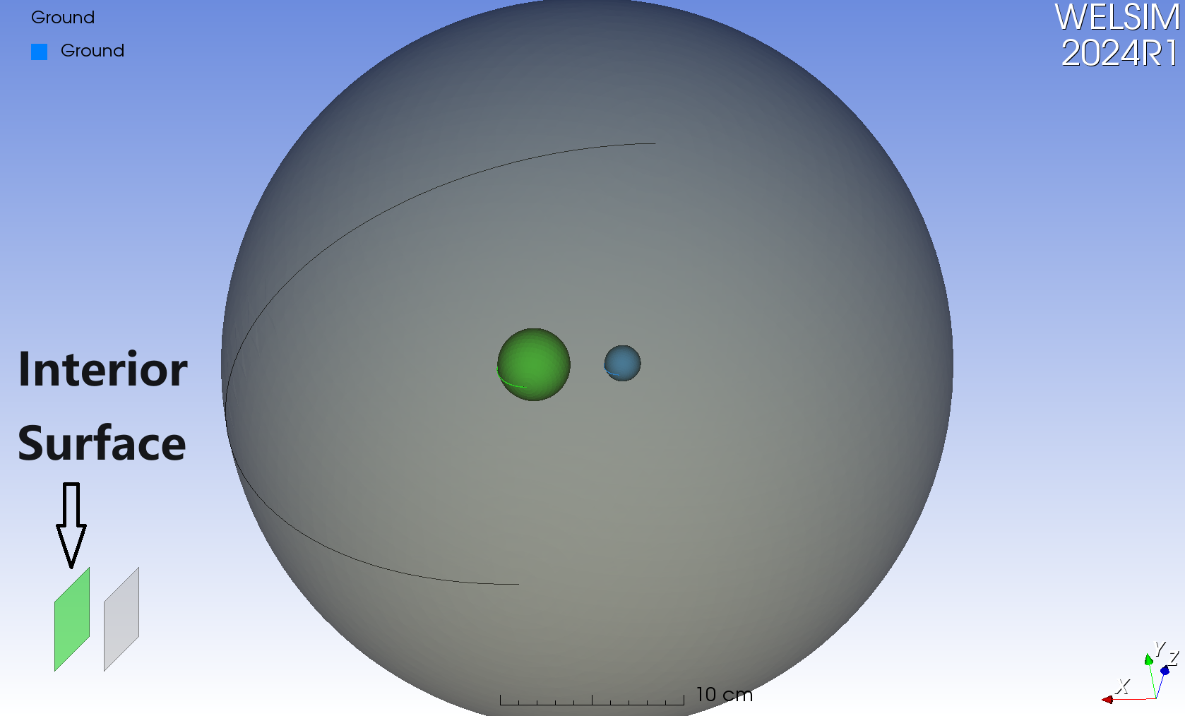
Moving the mouse to the left side of the layer view automatically selects the left layer. Now, the model updates the selected surface shown - the inner surface is now selected and highlighted in green.
The layer view simplifies the process of selecting inner surfaces. In this example, a spherical model demonstrates how to select the inner surfaces of 3D geometric bodies. The video demonstration is as follows:
This method is correspondingly applicable to other types of geometric bodies. When the position of the mouse click involves multiple surfaces, the layer view will display the corresponding number of layers. If the position involves fewer than two surfaces, the layer view remains hidden.
The layer view is a new feature introduced in the WELSIM 2024R1 version, primarily aimed at enhancing the pre-processing capabilities in three-dimensional fluid and electromagnetic simulations.
WELSIM is the #1 engineering simulation software for the open-source community.
reacted with thumbs up emoji reacted with thumbs down emoji reacted with laugh emoji reacted with hooray emoji reacted with confused emoji reacted with heart emoji reacted with rocket emoji reacted with eyes emoji
-
In three-dimensional CAE simulation analysis, it is often necessary to select interior surfaces of geometric bodies or choose surfaces that are occluded. This is applicable when setting up contact conditions for complex assemblies in structural analysis, defining boundary conditions for inner surfaces in electromagnetic, fluid, or thermal analyses, among other scenarios. Such requirements pose significant demands on the pre-processing modules of engineering simulation software.

Currently, a common approach in the industry is to add a selection layer view in a small region within the 3D graphics window. This feature displays the selection layers after clicking on a geometric body, enabling the user to modify the desired surfaces. This method is simple, intuitive, and provides a good user experience. However, this service adds extra software development work, as it requires incorporating an additional viewport in the 3D window. When implementing a selection layer view, the impact the feature has on the overall software performance must also be paid attention to.
Selection layer view
In the model below, there is a sphere with two small spherical cavities inside. When the model is set to be semi-transparent, the positions and sizes of the internal cavities can be observed. In 3D electromagnetic analysis, the exterior surface is often set as the far-field boundary, and various excitations are applied to the inner surface, such as voltage. Similarly, in fluid and thermal analysis, certain boundary conditions are set for the inner surface. In such cases, the GUI operation needs to be able to select the interior surfaces of the sphere.

When clicking on the position of the internal spherical cavity, the default outermost surface is selected and highlighted in green. If there are more optional surfaces, the layer view will be displayed. At this point, the layer view shows two layers: the unselected inner surface on the left, represented in gray; the selected outer surface on the right, highlighted in green.

Moving the mouse to the left side of the layer view automatically selects the left layer. Now, the model updates the selected surface shown - the inner surface is now selected and highlighted in green.

The layer view simplifies the process of selecting inner surfaces. In this example, a spherical model demonstrates how to select the inner surfaces of 3D geometric bodies. The video demonstration is as follows:
This method is correspondingly applicable to other types of geometric bodies. When the position of the mouse click involves multiple surfaces, the layer view will display the corresponding number of layers. If the position involves fewer than two surfaces, the layer view remains hidden.
The layer view is a new feature introduced in the WELSIM 2024R1 version, primarily aimed at enhancing the pre-processing capabilities in three-dimensional fluid and electromagnetic simulations.
WELSIM is the #1 engineering simulation software for the open-source community.
Beta Was this translation helpful? Give feedback.
All reactions