The USB port on the iSensor-SPI-Buffer is configured to act as a CDC type device, presenting as a virtual COM (serial) port.
The default windows virtual COM port driver should allow for communications.
The iSensor-SPI-Buffer virtual COM port exposes the same iSensor-SPI-Buffer register interface which can be accessed over SPI. In general, the functionality of each register should be the same, regardless of if the register is accessed over USB or SPI. The registers are accessed via a simple command line interface (CLI). This CLI allows a PC to interface with an IMU without the need for a SPI <-> USB board (like EVAL-ADIS-FX3).
The firmware can interface with a terminal emulator at a baud rate up to 1000000 bps. Since the device operates as a virtual COM port, baud rates less than that will work as well.
Putty or TeraTerm work well on Windows for manual interfacing with the CLI.
To enable easy data capture, a Python library has been written which handles interfacing with the iSensor-SPI-Buffer CLI. This library allows for easy iSensor-SPI-Buffer (and IMU) integration with an end user application, in both Linux in Windows.
The Python API exposes the following functionality:
- 16-bit register reads/writes
- Buffered data streams (data is captured in its own thread and placed into a Python queue)
- Support for all other misc helper CLI operations
The library also handles setting up the serial port (through PySerial) and configuration the buffer board - all the user application has to do is provide the portName.
The full documentation for the python library, source code, and Linux/Windows examples, are here
Several examples demonstrating typical use-cases for the CLI are linked below.
CLI Stream Tutorial for ADIS1649x IMUs
Commands are sent to the CLI over the virtual serial port. Interfacing with the SPI Buffer Board and ADI IMU follow the following structure:
COMMAND [ARG0] [ARG1] [ARG2]
Commands are case-sensitive and must include spaces between arguments. Command validation and execution is triggered by sending a new-line character (pressing ENTER). Some commands may have option arguments. The table below shows the possible commands and a brief description of their operation.
All values should be written in hexadecimal without the leading "0x"
| COMMAND | ARG0 | ARG1 | ARG2 | DESCRIPTION |
|---|---|---|---|---|
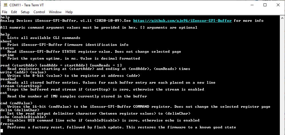
| help | - | - | - | List available CLI options |
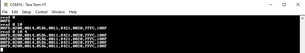
| read | Start Address | End Address | Number of Reads | Reads the value of a user-specified register or range of registers and prints their contents to the terminal. ARG0: Start address or register location to be read ARG1: Optional. End address of the register block to be read ARG2: Optional. Number of times to read the register block |
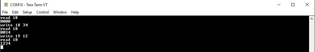
| write | Register Address | Byte to Write | - | Writes a byte (8-bits) to a user-specified register. ARG0: The register address to be written to ARG1: The byte (8-bits) to be written |
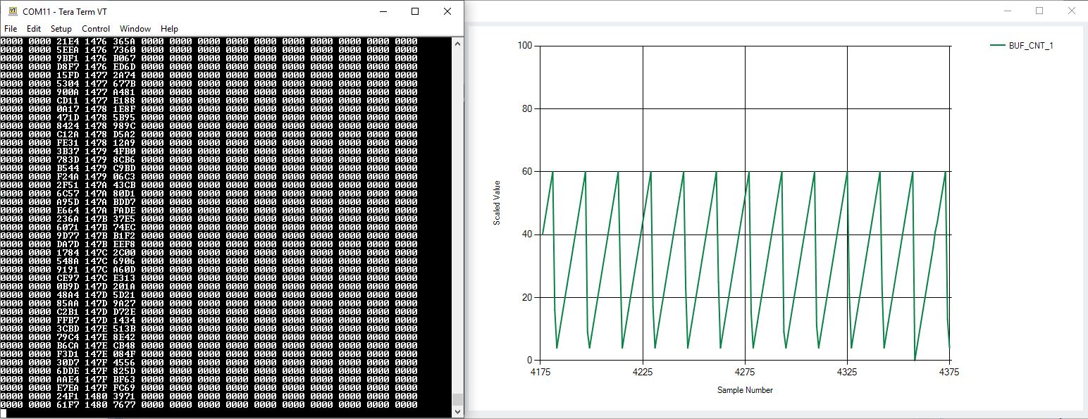
| stream | 0 or 1 | - | - | Continuously streams the contents of the SPI buffer (page 255) to the terminal. This command is equivalent to calling readbuf every time a watermark interrupt is generated. The length of each packet is determined by the BUF_LEN register.ARG0: [0] = stop the stream, [1] = start the stream |
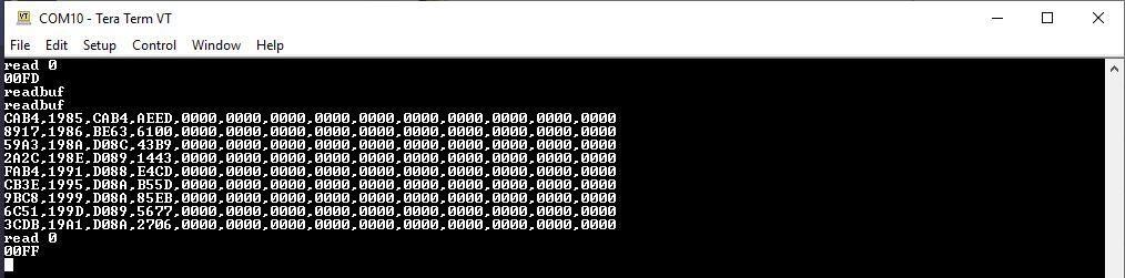
| readbuf | - | - | - | Reads the entire contents of the buffer and prints it to the terminal. Each buffer entry is divided using a new-line character (\n). Issuing this command will set the active page to 255. |
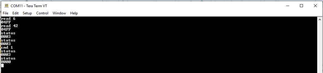
| status | - | - | - | Print the contents of the SPI Buffer Board STATUS register to the terminal. Issuing this command will clear all non-sticky status bits and will not change the currently selected page. |
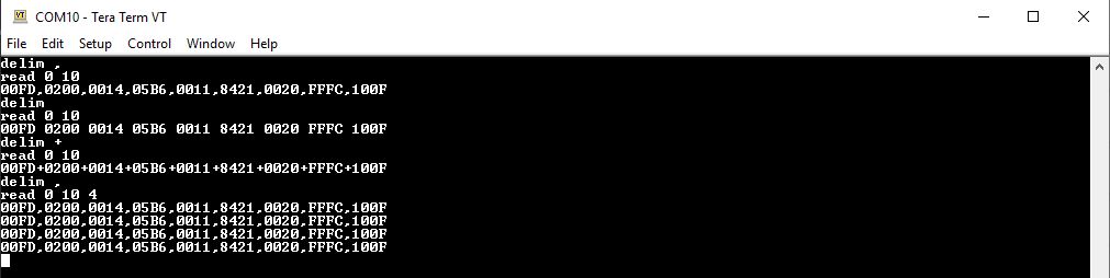
| delim | Delimiter Character | - | - | Sets the delimiter character inserted between register contents for all read operations. Any ASCII character can be used. The default delimiter used is a space. ARG0: Delimiter character |
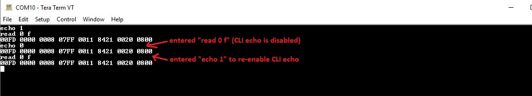
| echo | 0 or 1 | - | - | Controls the terminal echo configuration. When echo is disabled, characters sent to the SPI Buffer Board through the CLI will not be "echoed" back to the terminal. This setting is useful when interacting with the CLI using scripts. ARG0: [0] = disable terminal echo, [1] = enable terminal echo (default) |
| cmd | 16-bit USER_COMMAND Register Value | - | - | Writes a 16-bit value to the SPI Buffer Board USER_COMMAND register in a single CLI operation. The USER_COMMAND register description contains more information on the function of each bit. Issuing this command will not change the currently selected page. ARG0: 16-bit USER_COMMAND register value. |
| cnt | - | - | - | Prints the contents of the BUFF_CNT register to the CLI. The BUFF_CNT register shows the number of buffers stored in SPI Buffer Board memory. |
| freset | - | - | - | Execute the factory reset and flash update routines. Restores all SPI Buffer Board registers to their default values and commits them to NVM. |
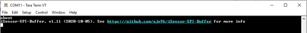
| about | - | - | - | Prints information about the SPI Buffer Board firmware. |
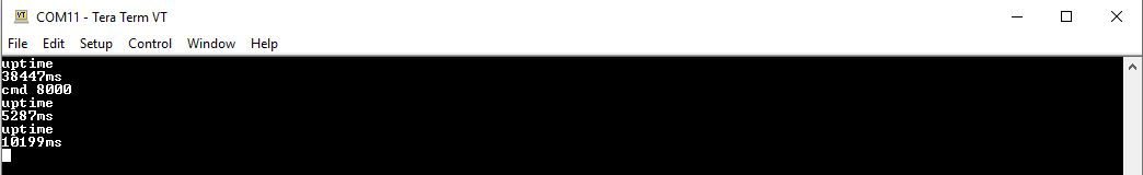
| uptime | - | - | - | Prints the firmware uptime in milliseconds. |
Help Command
About Command
Factory Reset Command
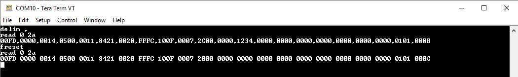
Register Read Command
Register Write Command
Cmd/Status Commands
Delim Set Command
Read Buffer Command
Stream Command (WATERMARK_INT_CONFIG set to 60)
Echo Command
Uptime Command