From Exercise Details:
On your final project board, make blinky for yourself. Then add a button to turn the LED on and off. Bonus points for making the button cause an interrupt. Triple bonus points for debouncing the button signal.
What are the hardware registers that cause the LED to turn on and off? (From the processor manual, don’t worry about initialization.)
My Initial VisualGDB project coincidentally happened to be a Blinky for RTOS.
Unfortunately, the default GPIO assignments for that tempate project
were incorrect. Instead of GPIO_PIN_12 and GPIO_PIN_13
I found that my board has LEDs LED1 on Port A GPIO_PIN_5
and LED2 on Port B GPIO_PIN_14 as shown in Table 2 in Chapter 7 of the
User Manual:

There are 2 buttons on my board: B1, RESET and B2 Wake-Up. Although not specified in the table above, there's indication on the schematic (page 43) of the
User Manual that the Wake-up button is
found on Pin 7, Port C GPIO13:

See also the B2 detail on page 51, noting in particular there's already a 100K pullup resistor, R23:

Additionally, note there's already a built-in RC debounce at C36, C37 and R24.
Can you read that memory directly and see the button change in a debugger or by printing out the associated memory?
There's a HAL function called HAL_GPIO_ReadPin
that by default when the switch is not pressed, returns a value of GPIO_PIN_SET ("on", which is expected, given the pullup resistor, and normally-open switch)

When single step debugging, and the button is then pressed, the next call to HAL_GPIO_ReadPin returns a value of GPIO_PIN_RESET ("off", which when pressed, pulls the line to ground)

The code for this HAL function is found in stm32l4xx_hal_gpio.c and looks like this:

One could read directly from (GPIOx->IDR & GPIO_Pin), although for code portability it is best to use the HAL.
See project files, in particular, main(). There are 2 separate RTOS threads for controlling LED1 and LED2.
The final version of my blinky uses the push button to control the mode of the LD2 LED:
IsBlinkingalternates between LED_ON() and LED_OFF()AlwaysOneven if theLED_OFF()is called, this mode ensure theLD2LED is always on.AlwaysOffeven if theLED_ON()is called, this mode ensure theLD2LED is always off.
As there are 2 LEDs the target blinky LD2, and the other, LD1 is used to indicate blinky mode:
IsBlinking-LD1blinks once, then pauses. repeat;LD2is blinking on 555ms duration on, and 555ms off.AlwaysOn-LD1blinks twice, then pauses. repeat;LD2stays on.AlwaysOff-LD1blinks three times, then pauses. repeat;LD2stays off.
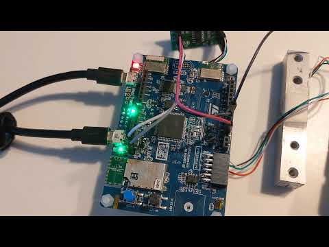
Here's a YouTube video of the blinky in action:
Why does the author use “marketing comes to you” through this chapter? How does it relate to previous chapters?
Pretty much every programmer knows that the requirements continually evolve and change for just about every project. Embedded development is no different. Often times, it is the marketing folks that have "insight" and new ideas of what consumers want.
I would prefer to use a HAL unless there were memory contraints. The HAL will typically be larger code size, but more easily portable between different target processors.
(to be done in class)
Given an input interrupt, output(s), and timers, what could you build? How many things are just a combination of these?
Limited by the imagingation! An output could trigger anything from a simple LED to a massive solid state relay controlling high-current / high voltage systems.
The LED initialization looks like this:
    __GPIOA_CLK_ENABLE();
    __GPIOB_CLK_ENABLE();

	GPIO_InitTypeDef GPIO_InitStructureA;

    GPIO_InitStructureA.Pin = GPIO_PIN_5;

    GPIO_InitStructureA.Mode = GPIO_MODE_OUTPUT_PP;
    GPIO_InitStructureA.Speed = GPIO_SPEED_FREQ_HIGH;
    GPIO_InitStructureA.Pull = GPIO_NOPULL;
    HAL_GPIO_Init(GPIOA, &GPIO_InitStructureA);


    GPIO_InitTypeDef GPIO_InitStructureB;

    GPIO_InitStructureB.Pin = GPIO_PIN_14;

    GPIO_InitStructureB.Mode = GPIO_MODE_OUTPUT_PP;
    GPIO_InitStructureB.Speed = GPIO_SPEED_FREQ_HIGH;
    GPIO_InitStructureB.Pull = GPIO_NOPULL;
    HAL_GPIO_Init(GPIOB, &GPIO_InitStructureB);
The Button initialization looks like this:
    // Initialize Port C
    GPIO_InitTypeDef GPIO_InitStructureC;

    GPIO_InitStructureC.Pin = GPIO_PIN_13;

    GPIO_InitStructureC.Mode = GPIO_MODE_INPUT;
    GPIO_InitStructureC.Speed = GPIO_SPEED_FREQ_HIGH;
    GPIO_InitStructureC.Pull = GPIO_NOPULL;
    HAL_GPIO_Init(GPIOC, &GPIO_InitStructureC);

    // create a SwitchState variable to hold the result of out button press
    GPIO_PinState SwitchState;
<< Exercise 3b -- Assignments -- Exercise 5 >>