Firmware Programming
The first installation of this firmware onto Gotek can be done either by serial or USB link to a host PC.
A nice video summary of this method using programming software on Windows is available on Youtube courtesy of Kris Cochrane. It also includes the OLED Display and Piezo Sounder mods, and shows how to set up in Autoboot mode with the HxC file selector:
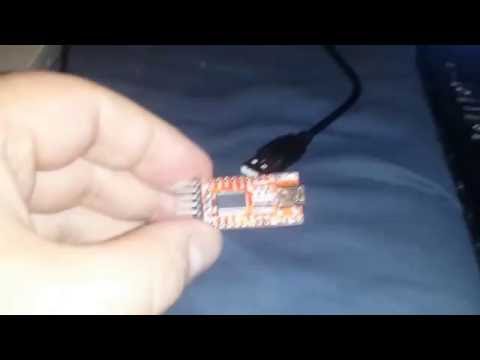
Serial programming requires a USB-TTL adapter, readily available on Ebay or from project webstores:
- CAB-12977 from SparkFun
- Search "PL2303HX usb ttl adapter" on Ebay, available for around one dollar.

The Gotek is then jumpered in system-bootloader mode and programmed from the host PC. See the below picture for wiring and jumper selection. This Gotek has had pins soldered to the programming header. It is possible to make the required connections with no soldering, but be careful that all wires are sufficiently well connected. Also note that the ordering of the connections (5V,GND,TX,RX) can vary across adapters, so be careful to note the ordering on your own.

The programming process is described, along with suitable Windows software, on the Cortex firmware webpage. Of course, rather than using the Cortex HEX file, use the *.hex file contained in the FlashFloppy distribution.
If programming on Linux, you can follow the Cortex instructions to physically set up your serial connection and bootstrap the Gotek, and then use stm32flash to do the programming:
 # sudo stm32flash -k /dev/ttyUSB0
 # sudo stm32flash -vw flashfloppy_fw/FF_Gotek*.hex /dev/ttyUSB0
- On Windows, ensure the driver has correctly detected the USB-TTL adapter. In particular, PL2303 clones have trouble with the official Prolific driver.
- Ensure you have TX and RX wires the correct way round.
- Sometimes the STM32 bootloader gets confused or negotiates the wrong baud rate. Try resetting the Gotek by touching NRST to GND, or by removing and reapplying power.
- Some serial adapters require pull-up resistors on the TX and RX wires. See AN2606 ("STM32 microcontroller system memory boot mode"), Section 3.3, Figure 1. A suitable resistor value (R) is 10K; these can safely be connected to VCC/+V of 3.3V or 5V.
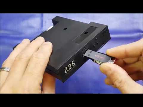
This method requires a USB-A to USB-A cable, and you should program the *.hex file contained in the FlashFloppy distribution. See this Youtube video for more details: