-
Notifications
You must be signed in to change notification settings - Fork 0
Abstraction
This uses PD0 and PD1. One blinks every 500ms and the other blinks every 1s program. When you run this program. You have to add the driver folder to your project properties include setting!

This uses PD2(RX) and PD3(TX). You can change the options in the usart.h and usart.c. Unfortunately, this example doesn't support any kinds of the queue which stores your input. So, you have to set your delay time as I do in main.c files.
In this example, I use the PL2303HX USB to TTL converter module.

I recommend the Putty to communicate with ATMega128 by serial. I think this site can help you to set up the communication between Putty and ATMega128 machine. If you connect correctly, then you can see the image like below.

This shows how to use the interrupt in ATMega128 with FreeRTOS. Most important things in this repository are below code.
ISR(USART_RX_VECT){
    BaseType_t xHigherPriorityTaskWoken = pdTRUE;
    xQueueSendFromISR(usart_interrupt_queue,
                      (const void *) &USART_UDR,
                      &xHigherPriorityTaskWoken);
    if (xHigherPriorityTaskWoken)
        taskYIELD();
}
You need to analyze attentively this part to fully understand this feature.

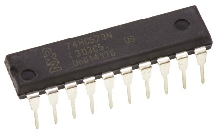
This is the example of how to use the D-FF_example. I was made this program using D Flip Flop which model name is 74HC573N(above image). This program uses PD0 to PD5. PD0 and PD1 use for set data. PD4 uses as a timer which makes to execute the D-Flip Flop. And PD5 uses to supply power. As a result, schematic for this program is like below image and program executes is like below video. (I set the timer to wake every 5000 system tick)
