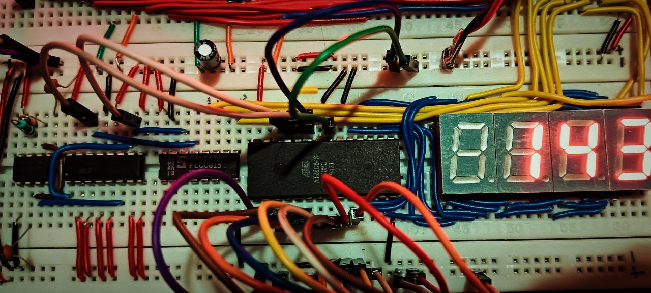
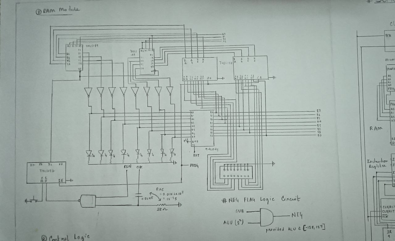
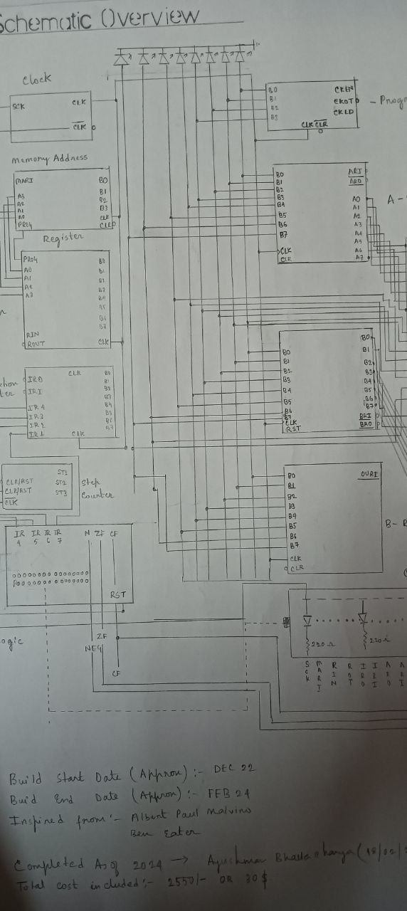
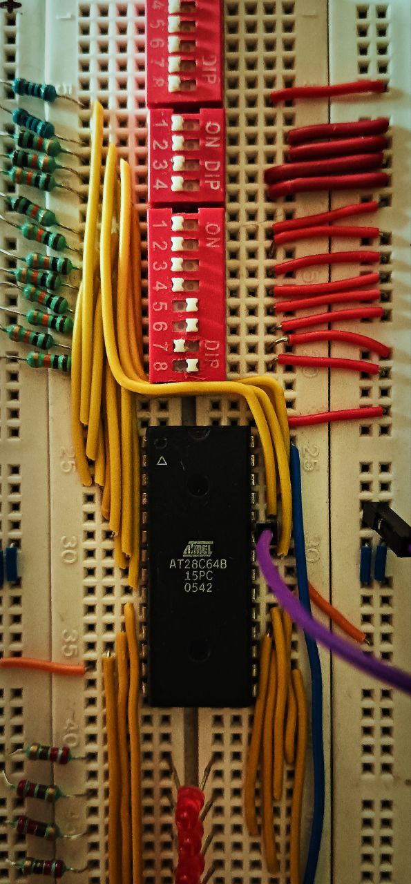
This repository contains the code, schematics, and documentation for a programmable 8-bit computer built from scratch using simple logic gates on breadboards. The project is open source and fully scalable, capable of integrating additional functions and ICs.
The computer is divided into several parts:
- PWM Clock
- Address Register
- RAM
- Instruction Register
- Control Logic
- Program Counter
- A Register
- B Register
- ALU (Arithmetic Logic Unit)
- Output Display
- Output Register
- Control Word
- Overflow, Underflow, Negative Flag Register
This project is inspired by and credits Ben Eater for the original idea and guidance. While based on his concepts, this implementation includes updates and differences, enhancing functionality and scalability.
- Scalability: Easily expandable with additional functions and integrated circuits.
- Custom Updates: Includes enhancements and modifications beyond the original design.
- Open Source: Available for anyone to study, modify, and contribute to.
code/: Contains the code for each component of the computer. CodeeepromFlasher/: Contains the code to flash OP Code into EEPROM for anyone following Ben Eaters Approach of Creating Control Logic. eepromFlasher.inoschematics/: Includes schematics and diagrams detailing the computer's architecture.Schematicsdocs/: Documentation, user manual, and design notes at Dedicated Docs Dropping Soon
- Clone the repository to your local machine.
- Refer to the documentation for assembly instructions, usage, and programming the computer.
- Explore and contribute to the project as desired.
##Changes
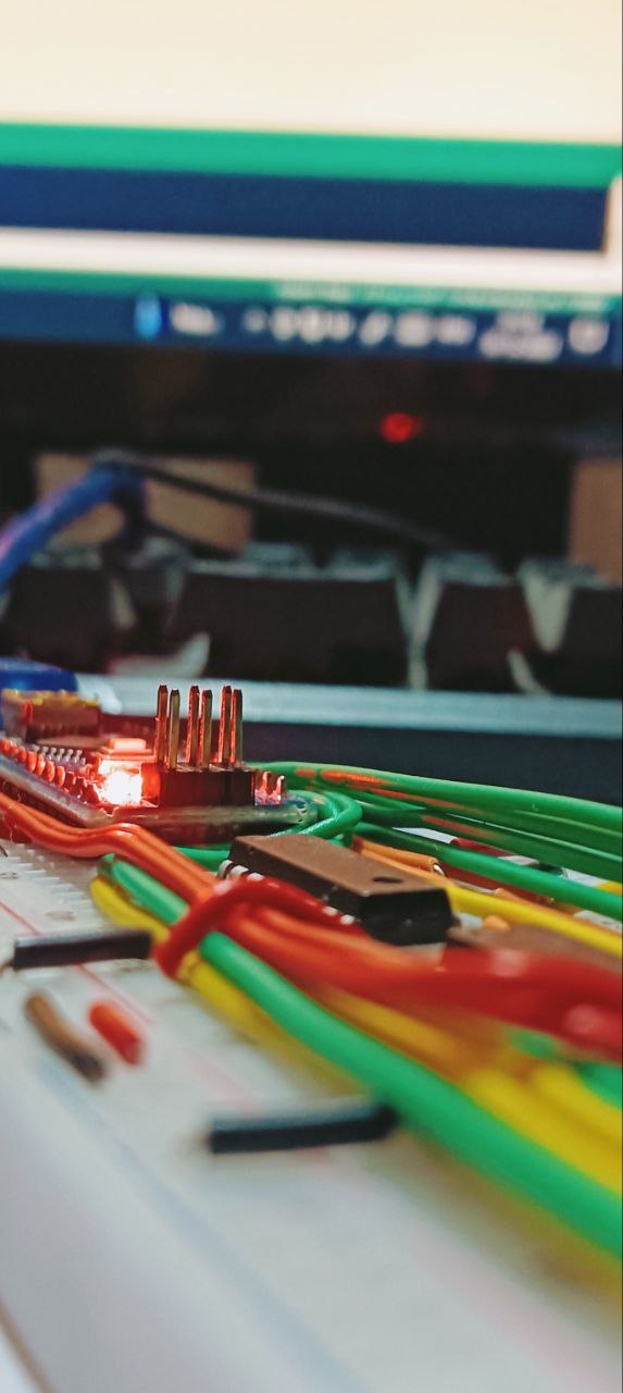
- Used Arduino Nano to drive control logic in place of ATC16 EEPROMS Code
- Added a negative flag register to the system [Specific Schematic will be Dropping Soon]
IF ALU_MSB == 1 and SUB = 1 THEN NEG_FLAG = 1- Updated the Code to detect negative number and push a -ve sign at the output display mux ![Specific Code will be Dropping Soon]
#define NFLAG 11;
pinMode(NFLAG, INPUT);

if(NFLAG == 1)
{
  negativeFlgFunc();
}- Updated the B register to be able to output contents to the BUS
- Updated the step counter to be able to count from (000)
2to (110)2Now the Step Counter can Count Upto 7 Steps, the current repo code has only 5 Steps without NOP) - Smoother Clock Speed with
20msdelay from Arduino and333HzPWM Clock.
Contributions are welcome! If you have ideas, improvements, or bug fixes, feel free to open an issue or submit a pull request.
This project is licensed under the MIT License.
