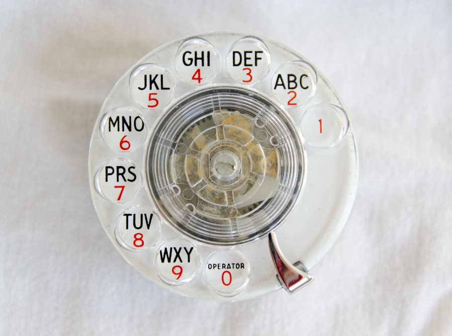
Phone that takes input from a rotary dial(check Wikipedia: Rotary dial).
The dial produces pulses where [1, 9] pulses correspond to the numbers [1, 9], and 0 is represented by 10 pulses. Similar to the dial demonstrated here and pictured above.
The expected circuit is:
     Rotary Dial                              Arduino
                      /---------------------- readyPin (pin 7)
  /- ready switch (NO) -- pull-up resistor -- VCC
 /-- pulse switch (NC) -- pull-up resistor -/
 \                    \---------------------- pulsePin (pin 8)
  \------------------------------------------ GND


     HT1621 DISPLAY
        pin 1  ------------------------------ VCC
        pin 2  --470 ohm resistor ----------/
        pin 3  ------------------------------ GND
        pin 4  ------------------------------ DATA  (pin 11)
        pin 5  ------------------------------ WD    (pin 10)
        pin 6  ------------------------------ ~CS   (pin 12)


     INPUT BOARD
                       /--------------------  callPin (pin 9)
  /- Call Button  -- pull-up resistor ------- VCC
 /-- Back Button  -- pull-up resistor ------/
 \                     \--------------------- backPin (pin 6)
  \- Clear Button -- pull-up resistor ------- VCC
   \                   \--------------------- clearPin (pin 5)
    \---------------------------------------- GND


     SIM 800L
        VCC  ------------------------------ 4.2V BAT INPUT
        GND  ------------------------------ GND
        RXD  ------------------------------ Software Tx  (pin 2)
        TXD  ------------------------------ Software Rx  (pin 3)
        RING ------------------------------ Call_Detect  (A3)

     SIM 800L TO RECEIVER
        MIC +,-  -------------------------- ELECTRET MIC
        SPK +,-  -------------------------- 8 ohm SPEAKER
I soldered everything to a prototyping board and powered the board with two 18650 cells in parallel.

👍 The circuit looks great and ready to take on some calls ![]()

