pl_Create Skeleton Sketch
This tutorial is a replication of SolveSpace linkage tutorial. In order to assemble the following linkage system,
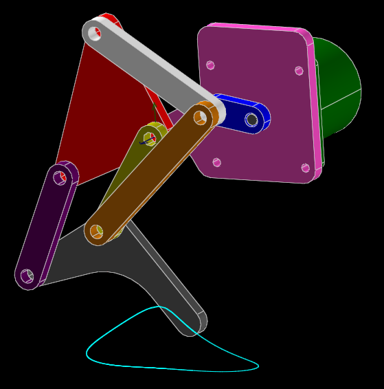
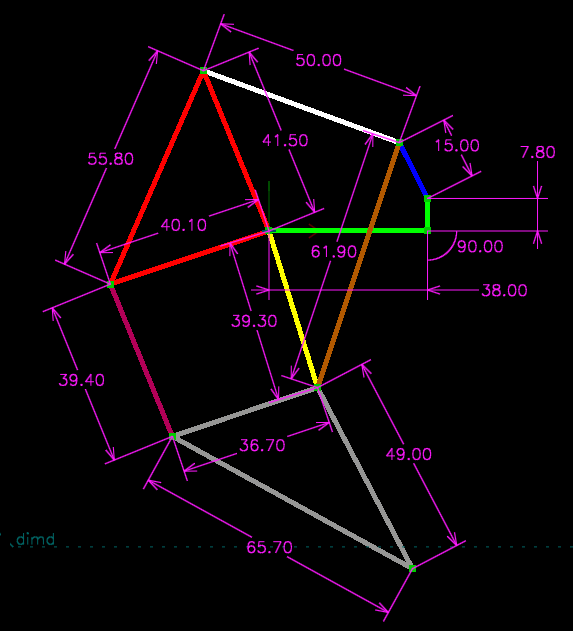
we are going to build a skeleton sketch as follow,
- Switch to Assembly3 workbench
- Create an empty assembly container
- Select the newly create assembly object, and click
 to add a work plane. Note that you can use any other object with planar edge or face to define the sketch plane. The Assembly3 work plane is just a convenience.
 - This is an optional step, change the plane
WidthandLengthto 100mm, and then scale and position the 3D view to put the entire plane in the center. Then hide the plane to not interfere with the draft object editing. The sizing of the plane is to give you a rough idea of how long the lines should be. It is suggested to draw the initial sketch close to the final structure to avoid confusing the solver. - Select the new work plane, and click
 to add a
 sketchPlaneconstraint - Now, switch to Draft workbench
- Add a few wires according to the above picture. You can add one wire for each colored lines, or you can use multi-segment wires as much as possible to reduce the number of point coincidence constraints needed later.
- This is an optional step. For two point line segment, you can set the
Lengthproperty of the draft wire to define the length now. For multi-point poly-lines, you can set the length in later step. - Drag all draft wires into the assembly container.
- For the green three-point poly-line, you can select any one of the three points, and click
 to create a
 Lockedconstraint to fix that point. - Select the vertical green line segment, and click
 to create a
 LineVerticalconstraint. - Select the horizontal green line segment, and click
 to create a
 LineHorizontalconstraint. - For each line segment, select and click
 to create a
 LineLengthconstraint to fix the length. The initial length parameter is calculated from the selected line. So if you have already set the draft wireLengthproperty, there is nothing else to be done. For other lines, set theLengthparameter of the constraint accordingly. - Select pairs of points according to the picture above, and click
 to create a
 PointsCoincidenceconstraint. - To trace the movement of an vertex, select it first, and then click
 . If you have enabled tracing before, you'll need to disable it first before selecting a new vertex and enable it again. If you select an edge or face, then you will be tracing the center point of the shape. If you don't select any shape before enable tracing, you will be tracing the moving shape.
 - Select any vertex/edge/face you want to move, and click either
 or
or  and then drag the arrow to move.