Replies: 5 comments 9 replies
-
|
Hi there. Thanks, |
Beta Was this translation helpful? Give feedback.
-
|
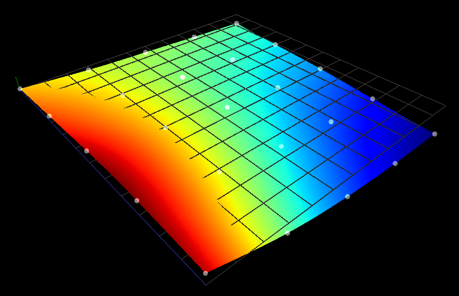
I like your CNC machines. Ok. I think I understood your problem and I'll try to help the best way I can. Surface correctionEven if you have a very flat surface, bended linear guides (apart from some possible problems in the motion of the machine) will make your machine (gantry, tool or bed) move in an non linear way. Like this image: In that case I think the best possible solution is to use a surface mapping that modifies the Gcode on the fly to compensate for that. If you need to do it in firmware then Marlin or Klipper might be an alternative. I recommend getting a Renishaw probe or similar (or building one) to do the mapping surface. About the suggestion of using an accurate rod to measure any distortion of the axis there are 2 problems with that.
Axis non perpendicular (skew)Yes µCNC as that implemented and can be enabled. It works like skew in Marlin. Once enable 2 additional settings will be available to enter the correction factors. The factors are calculated like in Malin. Here is the explanation from Marlin firmware: I'm going to be honest. A precision of 0.01mm or lower is not easy on a hobby machine. If you need other or more complex software corrections than you might want to consider using LinuxCNC. One final note. You don't have to donate anything. I'll gladly help you in any way I can. Hope I've covered your questions. Regards, |
Beta Was this translation helpful? Give feedback.
-
|
That might work but only partially. I'll try to explain my thoughts on the matter. If I'm understanding right you are building a moving gantry type of machine (like your CNC and CNC1). That is a fixed bed and a gantry that moves the in the Y direction. The gantry carries the tool and moves it X and Z. That plan of yours might work for X (were the tool moves right and left) because the linear guides are close to each other. But for the Y it may not. Unless you have exactly the same bending on both Y linear guides of your machine the gantry will not move in the Y axis in an uniform way. If the bending happens in different places the deformation will not be a wave but a concave/convex plane. I have 2 suggestions for you. Either get a super flat surface and do the surface scanning there. Or use your method on both sides of Y axis. In excel you should be able to generate an hmap for OpenCNCPilot ( that is nothing more than a XML file with the mapped points) and see if this fixes the motion for you. Once done apply the same hmap to all your running Gcode. Remember your origin reference must always be the same. I you move your homing point from there you have to repeat the process. Have you tried help in other forums? I think that I've seen some concrete epoxy CNC builds over at www.cnczone.com Hope it helps. |
Beta Was this translation helpful? Give feedback.
-
|
Just one more note. I think you should probably address the skew issue before mapping. |
Beta Was this translation helpful? Give feedback.
-
|
Hi. Best regards. |
Beta Was this translation helpful? Give feedback.


-
Hi.
I have idea add functions to solve mechanical problem in CNC (right angle, axe deviation .. etc .).
Using calibrated rod , measure errors and then save to firmware, function use this data and in motion
adapt .
Paciente8159 give my your email pls .
regards.
Beta Was this translation helpful? Give feedback.
All reactions