
Introduction • Specifications • Block Diagrams • Flowchart • Results
A digital communication system utilizes a mode of communication where information is encoded digitally as discrete signals and electronically transferred to the recipients. Digital communication systems are omnipresent and play a vital role in today’s world. With the right technology, data can be transmitted over a large distance.
A typical digital communication system consists of a transmitter, a channel and a receiver. The digital data (0s and 1s) is typically “modulated”, i.e., converted into signals which are optimised for transmission. The modulated signal is transmitted over a channel, where noise gets added. Signal loses power i.e. signal attenuation occurs and this loss is generally different for different frequencies. Hence, the channel also acts as a filter. Finally, at the receiving end, there is a demodulator which converts the waveforms back to digital information.
Since the received signal is not exactly the same as the transmitted signal, there will sometimes be errors in the received information. These errors can be quantified numerically if information about the channel is known.
In this project, we simulate a complete digital communication system whose details will be shared in the further sections.
The system functions on the following received parameters:
- Bit Energy
- Bit Time
- Carrier Frequency
- Sampling Frequency
- Noise Power Spectral Density
- Input Signal
- Whether or not to apply coding scheme (discussed later)
Information is received from the user and converted to bits. These bits are encoded for error correction (more on that later). Thereafter, the bits are modulated. We simulate the following modulation techniques:
-
Binary Phase Shift Keying (BPSK)
-
Quadrature Phase Shift Keying (QPSK)
-
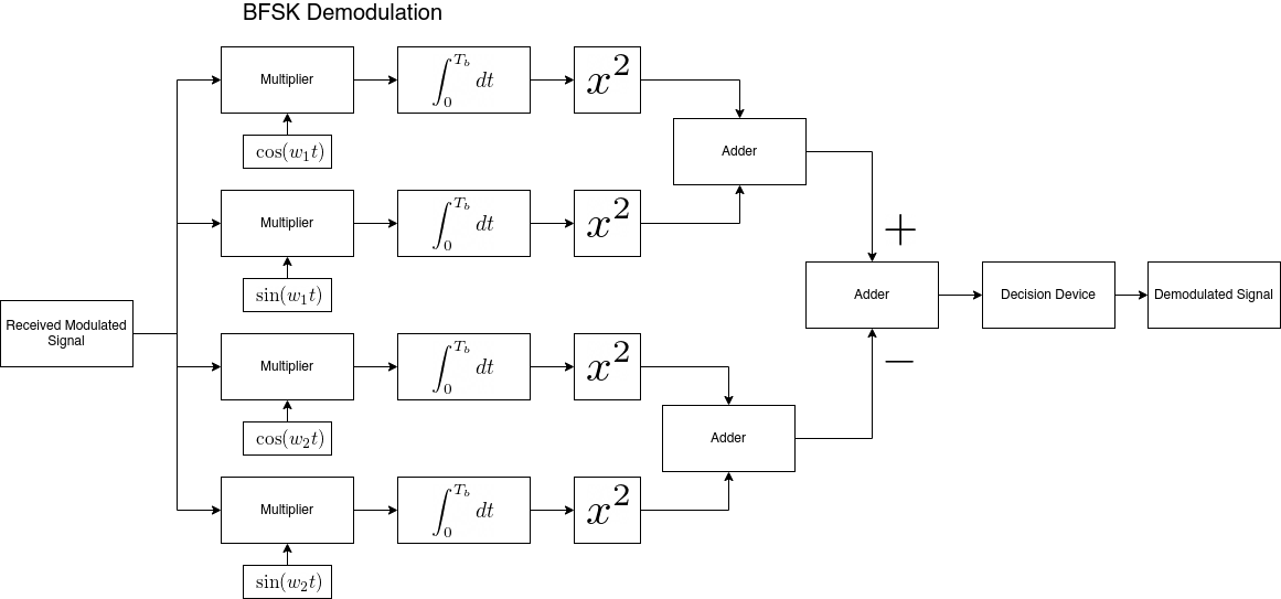
Binary Frequency Shift Keying (BFSK)
-
Quadrature Frequency Shift Keying (QFSK)
We have also attempted to generalize PSK by writing code for M-Ary Phase Shift Keying (MPSK) which can perform modulation/demodulation for a given value of 'M'. But since the error performance was highly unsatisfactory, we are not using it. (Pull requests welcome!) Data given by the user is modulated using the technique of his choice and converted to waveforms.
The channel is simulated by adding Additive White Gaussian Noise (AWGN) of the desired Power Spectral Density. The noise distorts the waveforms. Finally, the signal is demodulated and the bit error rate is calculated. The same is compared with the theoretically expected value. The noteworthy characteristics of Additive White Gaussian Noise which need to be considered are:
-
The samples follow a normal distribution in the time domain, i.e., they follow a Gaussian distribution with mean 0 and variance 1.
-
The power across the frequency band is uniform.
-
The samples are assumed to be independent and identically distributed (iid). Practically, it would be impossible to generate such a signal. But we can approximately obtain it. Following is the distribution of power spectral density across frequencies for 1000 samples we generate:
We infer that the values are comparable when a large number of bits are transmitted. The same will be discussed in the results section.

The receiver demodulates the signal based on the chosen method of demodulation. Thereafter, the signal is decoded using the extended Golay decoding scheme. For the sake of demonstration, we perform bit error analysis where the theoretical and practical values are compared. The same is discussed in the results section.
We use extended binary Golay code G24 to reduce the Bit Error Rate (BER). The extended Golay code encodes 12 bits of data in 24 words such that any 3-bit errors can be corrected or 7-bit errors can be detected. The standard coding notation for this code in terms of [n,k,d] is [24,12,8]. We use an existing Python implementation found in a GitHub repository and modify it for our purposes. (See credits) The bit error probability formula changes in this case and that is,
Where pc is the bit error probability without encoding, t is the number of correctable errors (3) and n is the encoded size (24).
- Python as the primary language
- SciPy and NumPy for scientific computation, inbuilt functions and array operations
- Matplotlib for testing on backend and error analysis
- Plotly Dash for the web application with dynamically updating results.


These results were generated by performing Monte Carlo simulations to generate an array of random samples and transmitting it over our AWGN channel. The BER was calculated by comparing the received and sent array of samples.
 |
 |
|---|---|
| Theoretical | Practical |
 |
 |
|---|---|
| Theoretical | Practical |
 |
 |
|---|---|
| Theoretical | Practical |
 |
 |
|---|---|
| Theoretical | Practical |
Image transmission (image used)
This was done by converting the image to a matrix of RGB values. Each value in that matrix was converted to binary and the obtained matrix was transmitted over our AWGN channel. At the receiving end, the matrix is again converted to the matrix of RGB values from which the image is generated.
 |
 |
|---|---|
| Sent | Received |
|
 |
|---|---|
| Sent | Received |
|
 |
|---|---|
| Sent | Received |
|
 |
|---|---|
| Sent | Received |
 |
 |
 |
 |
|---|---|---|---|
| Prayag Savsani | Yashraj Kakkad | Kaushal Patil | Dhruvil Dave |
This software uses code from the following open source repositories:
BSD 3-Clause "New" or "Revised" License