UMK4x4 V2.5 User Manual
      __ __| |           |  /_) |     ___|             |           |
         |   __ \   _ \  ' /  | |  / |      _ \ __ \   |      _` | __ \   __|
         |   | | |  __/  . \  |   <  |   |  __/ |   |  |     (   | |   |\__ \
_| _| |_|\___| _|\_\_|_|\_\\____|\___|_| _| _____|\__,_|_.__/ ____/Revision History
| Document Version | Firmware Version | Date | Changes |
|---|---|---|---|
1.0 |
2.5.0 |
May. 10, 2020 |
Initial Version |
1.1 |
2.5.2 |
Oct. 21, 2023 |
Velocity curves pipe |
© The KikGen Labs 2018-2023.
The content of this manual serves the purpose of providing non-binding information only and shall not be construed as a commitment of any kind by The KikGen Labs and can be subject to change at any time without notice. Despite making every effort to ensure that the information contained in this manual is accurate, The KikGen Labs shall not be liable for potential errors or inaccuracies.

The story of this project starts with a hack of the MIDIPLUS/MIDITECH MidiFace 4x4 USB to MIDI interface. Needing more midi jacks, I bought a second Miditech interface, but I discovered it was not possible to use 2 interfaces on the same computer to get 8x8. This is mainly because of identical product/vendor ID and serial, and, according to the Miditech support, as that usb midi interface is not updateable at all, I was stucked…. That was motivating me enough to go deep in the detail, and try, at less to change the PID or VID.
You can read about the detailed hack here : The Miditech 4x4 hack and STM32Duino.
The 2.5 is a major release of USBMIDIKLIK4x4 (aka UMK4X4), and is not compatible with previous versions. This manual describes how you can communicate and configure UMK4x4 with the host computer via the USB link.
16 MIDI USB IN / OUT |
16 USB ports available from the host. Support 15 physical JACK IN / 15 JACK OUT in bus mode. |
8 virtual ports |
8 internal virtual ports available for routing purpose |
4 midi clock generators |
Support until 4 internal midi clocks / Midi Time code (MTC) |
Full remote Configuration |
Configuration by SYSEX commands and/or and interactive menu from a serial USB terminal |
Large Sysex flow support |
Unbuffered SYSEX processed on the fly allowing unlimited messages size |
Complex routing rules |
Configurables by sysex or from an interactive user menu; allowing MIDI MERGE, SPLIT easily on any ports available. Ability to route any USB IN to any USB OUT/ MIDI OUT. |
Midi messages transformation engine |
Powerfull "pipeline" feature allowing to modify an incoming midi message within a chain of transformation functions, e.g., transpose notes, split, map channel to another, map CC to another, etc…. |
USB identification customization |
USB device ProductStringName, Vendor and Product Ids can be changed easily by the user |
STANDALONE Mode |
MIDI routing without connecting any host to the USB |
Intellithru mode |
Possibility to define a second level of routing rules automatically activated when USB is idle or unavailable after a certain delay |
Stackable interfaces |
Until 5 interfaces can be "stacked" in "bus mode" , to get 6x6, 9x9, 15x15 physical midi ports and 16x16 USB. |
STM32F103 full support |
STM32F103C8 / STM32F103CB / STM32F103RB / STM32F103RC uC support. Bluepill and Miditech 4x4 board support. |
UMK4X4 can be used in two ways : the USB host mode or the standalone mode.
Host USB mode allows the interface to be used with MIDI software when connected to a computer, called a "host.
Standalone mode allows the interface to be used without connection to the host, powered only by the USB port with, for example, a phone charger. In this mode only the DIN midi jacks are used.
An intermediate USB mode, called "Intelligent Midi Thru" (ITHRU), allows to switch to standalone mode if no midi message is received after a certain user-defined delay.
From the version 2.0, the "bus mode" allows to aggregate until 5 boards, each hosting a Bluepill , forming then a one virtual 15x15 ports interface (see bus mode section).
UMX4X4 can be installed or adapted to a great variety of boards based on the STM32F1 microcontrollers, and especially the STM32F103.

The STM32F103C8T6 board — also called Blue Pill (picture above) — is the preferred board for UMK4x4 because of its low cost (around 2$) and the 3 IN / 3 OUT midi ports capability. Obviously, the Miditech Midiface 4x4 (4 midi in/out) can be used, as it was the original POC for this project.
I have also designed a board, which can be considered as a "midi shield" for the bluepill, to easily transform that cheap uC board to a powerful 3 IN/OUT MIDI compliant interface.

The board is USB Powered, so no additional power supply necessary. It works driverless as a class compliant device, with Windows XP SP3, Vista 32 and 64 Bit, Windows 7 / 8 / 10 32 and 64 Bit, and Mac OS X, Linux ALSA, Akai MPC Live/X/Force, IOS, Android.
Some units are currently available at Tindie :
UMK4X4 provides three to four MIDI interfaces (and more in bus mode), each of which has an input and an output port. Only one application at a time can access a port. The midi 1 port is used to set special functions of UMK4x4 by using proprietary SYSEX messages. These messages are ignored on other ports.
The sysex system exclusive ("sysex") commands are vendor-specific MIDI messages used to configure UMK4X4 and retrieve device states.
All sysex messages to and from UMK4X4 have the format given in the table below.
Sysex messages sent to UMK4X4 are called commands, messages sent back to the host are called replies. UMK4X4 sends replies only as reaction to commands, no spontaneous sysex messages are sent. The reply id is most of the time equal to the corresponding command id, although the argument list usually differs.
Commands should not be nested. Before sending the next command the host should wait for the reply, if any is expected, of the previous command. Otherwise, pending replies might be dropped.
SYSEX ARE ONLY INTERPRETED ON CABLE 0 OR MIDI IN JACK 1.
The system exclusive messages format is the following :
| Message Data | Description |
|---|---|
0xF0 |
SOX (start of sysex) |
0x77 |
Manufacturer. The KikGen Labs sysex ID. Know that it is a totally unofficial Id. |
0x77 |
Device ID. Probably not needed for USB devices, but this is what most manufacturers do. |
0x78 |
Model ID |
ID |
Command or reply ID (7 bits unsigned integer) |
Arguments |
A number of 7 bit values depending on command or reply ID |
0xF7 |
EOX (end of sysex) |
Example: [ F0 77 77 78 06 08 F7 ] = command with ID 0x06 and argument 0x08 |
|
This is the list of sysex commands. The details are given in the respective sections.
| Command ID | Sub command |
|---|---|
0x00 Hardware reset |
|
0x01 Identity request |
|
0x02 Sysex acknowledgment toggle |
|
0x03 Sysex acknowledgment |
|
0x04 Factory settings |
|
0x05 Clear all midi, Ithru routing rules and pipelines |
|
0x06 Save settings to flash memory |
|
0x08 Reboot in configuration mode |
|
0x09 Reboot in update mode |
|
0x00 Set USB product string |
|
0x01 Set USB vendor id and product id |
|
0x00 Enable/disable midi clock |
|
0x01 Set midi clock bpm |
|
0x02 Enable/disable Midi Time Clock |
|
0x00 Reset to default |
|
0x01 Disable |
|
0x02 Set USB idle |
|
0x03 Set jack routing |
|
0x00 Reset to default |
|
0x01 Set midi port routing |
|
0x00 Enable bus mode |
|
0x01 Set device Id |
|
Slot operations : |
|
Pipe operations : |
F0 77 77 78 05 <dump address:nn nn nn nn> F7

-------------------------------------------------------------
| Dump data             | Dump address
-------------------------------------------------------------
| All                   | 7F 00 00 00
| USB device settings   | 0B 00 00 00
| Midi clock settings   | 0C <clock#:0-8> 00 00
| USB Idle              | 0E 02 00 00
| IThru routing         | 0E 03 <Jack In> 00
| In port midi routing  | 0F 01 <in port type:0-2> <in port>
| Bus mode settings     | 10 00 00 00
| In port attached slot | 11 00 <in port type:0-3> <in port>
| Pipes in slot         | 11 01 <slot> <pipe index>
-------------------------------------------------------------
Clock #: 0-8    in port: 0-F
port type : cable = 0 | jack = 1 | virtual:2 | ithru = 3
06 00 Hardware reset
F0 77 77 78 06 00 F7

06 01 Identity request
F0 77 77 78 06 01 F7

06 02 Sysex acknowledgment toggle (on/off)
F0 77 77 78 06 02 F7

06 03 Sysex acknowledgment (received/never interpreted)
F0 77 77 78 06 03 <ack> F7

06 04 Factory settings
F0 77 77 78 06 04 F7
The device will reboot after the command.

06 05 Clear all (midi, Ithru routing rules and pipelines..)
F0 77 77 78 06 05 F7

06 06 Save settings to flash memory
F0 77 77 78 06 06 F7

06 08 Reboot in configuration mode
F0 77 77 78 06 08 F7

06 09 Reboot in update mode
F0 77 77 78 06 09 F7
0B 00 Set USB product string
F0 77 77 78 0B 00 <usb product string not accentuated> F7

0B 01 Set USB vendor ID and product ID
F0 77 77 78 0B 01 <vendor id:nn nn nn nn> <product id:nn nn nn nn> F7
0C 00 Enable/disable midi clock
F0 77 77 78 0C 00 <clock #:0-3> <disable:0 enabled:1> F7

0C 01 Set midi clock bpm
F0 77 77 78 0C 01 <clock #:0-3> <bpm: msbn lsbn1 lsbn2> F7
Each 4 bits hex digit nibble must be serialized from the MSB to the LSB.
Bpm value must be x 10, and between 100 (10 bpm) and 3000 (300 bpm)

0C 02 Enable/disable Midi Time Clock
F0 77 77 78 0C 02 <clock #:0-3> <disable MTC:0 enabled MTC:1> F7

If clock # = 7F, then all clocks are updated (MTC must be set individually).
Due to the frequency of change, the clock state or BPM are not stored into
the flash memory after the execution of the sysex command.
However, the global function "Save settings" (06) can be used to save clocks.
0E 00 Reset to default
F0 77 77 78 0E 00 F7

0E 01 Disable all
F0 77 77 78 0E 01 F7

0E 02 Set USB idle
F0 77 77 78 0E 02 < Number of 15s periods: 00-7F > F7

0E 03 Set jack routing
F0 77 77 78 0E 03 <JackIn port > [<out port type> [<out ports list: nn...nn>] ] F7
Allowed port type : jack=1 | virtual=2   port:0-F  out port type/ports list are optional.
If only jackin is passed, this toggle on/off IThru if output ports exist.
If no out ports list passed, the entire out type will be cleared.
Refer also to appendices for more examples.
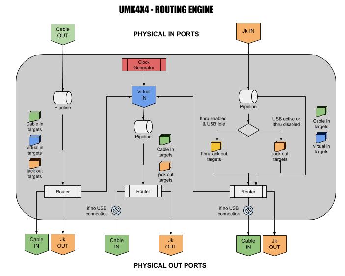
Any IN port can be routed to any OUT port.
4 Midi clock generator / 8 virtual ports are available within the routing engine.
Below is an overview of the possible paths for a midi message packet, coming from a physical in port to a physical out port :
Sysex routing commands :
0F 00 Reset to default
F0 77 77 78 0F 00 F7

0F 01 Set midi port routing
F0 77 77 78 0F 01 <in port type> <in port> <out port type>[out ports list: nn...nn] F7
port type : cable = 0 |jack=1 | virtual=2   port : 0-F out ports list is optional.
If no out ports given, the port routing will be canceled.
A virtual port can't be routed to another virtual port.
Regarding bus mode, please refer also to appendices.
10 00 Enable/disable bus mode
F0 77 77 78 10 00 < enable:1 | disable:0 > F7
The device will reboot after the command if bus state changed.

10 01 Set device ID
F0 77 77 78 10 01 < deviceid:04-08 > F7
deviceid must be set to 4 when master.
The device will reboot after the command if id changed.
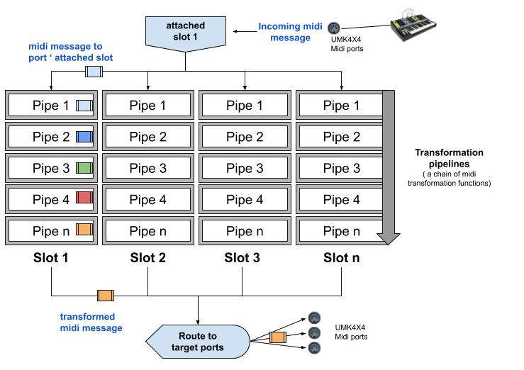
The "pipeline" feature allows you to apply transformation of an incoming midi message through a chain (a "slot) of transformation functions (a "pipe"), e.g., transpose notes, split, map channel to another, map CC to another, etc…
The first step is to attach a midi in port to slot, so all midi events will pass through the slot and undergo transformations.
The second step consists in defining what will be the transformation sequence, by adding pipes in the selected slot. Until 8 pipes can be easily chained to obtain complex midi transformations without degrading performances.
Pipes are the following :
| ID | Description |
|---|---|
MSGFLTR |
Filter midi message depending on particular conditions |
NOTECHG |
Transpose midi notes by semitones |
CHANMAP |
Change the source midi channel to another |
VELOCHG |
Modify note velocity, or filter notes depending on velocity value |
CCCHANG |
Modify a Control Change (CC) value to another, or filter a specific CC |
CLKDIVD |
Divide an incoming midi clock message by a specific ratio |
LOOPBCK |
Route again a midi message to any IN port (loopback) |
SLOTCHN |
Chain current slot to another existing slot |
KBSPLIT |
Keyboard split |
VLSPLIT |
Velocity split |
VLCURV1 |
Set 4 values of the velocity curve |
VLCURV2 |
Set a single linear segment of a velocity curve |
VLCURV3 |
Velocity curve between 6 presets |
Pipes can be repeated within the same slot. For example, if you need to split your midi keyboard to 4 different areas, you can add 2 KBSLPIT pipes in the same slot, so notes will be affected to 4 different midi out channels.
3 pipes are available to adjust the velocity of played midi in notes.
VLCURV1 : Velocity curve 4 values
This pipeline allows you to define 4 values, that will form a 5 segments velocity "curve" affecting midi out :
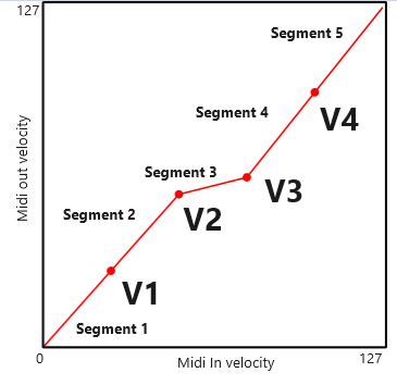
Intervals are defined as follows :
| # | Midi in velocity range |
|---|---|
1 |
[ 0 , 25 ] |
2 |
] 25 , 50 ] |
3 |
] 50 , 76 ] |
4 |
] 76 , 101 ] |
5 |
] 101, 127 ] |
VLCURV2 : Linear velocity curve segment
This pipeline allows you to define a single linear segment of the velocity curve with 2 (midi in, midi out) pairs. You can use that to define a fully customized curve, by adding, for example, 6 VLCURV2 pipes in the same slot that will form 7 segments on top of the velocity curve. It can be combined with VLCURV1, or VLCURV3 to fine tune the resulting velocity curve. It is important to note that VLCURV2 applies ONLY on the original midi packet velocity, i.e. before any transformation.
The graph below shows an example combining pipes VLCURV1(40,15,80,90) and VLCURV2(120,120,127,90):

VLCURV3 : velocity curve presets
This pipeline allows you to choose a predefined velocity curve between 6 presets : compressed for hard player, medium velocity, compresser/expander, low velocity 1 & 2, top and bottom ends cut.

Preset midi velocity xIn,yOut values :
| # | 1. Compressed for hard players | 2. Medium velocity : compressed dynamics | 3. Compresser/Expander : Low values then high | 4. Low Velo 1 : Extreme compression; Low values | 5. Low Velo 2 : Extreme compression; Low values | 6. Compressed : Top and bottom ends cut |
|---|---|---|---|---|---|---|
1 |
[ 0 , 0 ] |
[ 0 , 0 ] |
[ 0 , 0 ] |
[ 0 , 0 ] |
[ 0 , 0 ] |
[ 0 , 0 ] |
2 |
[ 32 , 16 ] |
[ 16 , 48 ] |
[ 13 , 29 ] |
[ 8 , 8 ] |
[ 8 , 8 ] |
[ 6 , 24 ] |
3 |
[ 64 , 32 ] |
[ 95 , 64 ] |
[ 105, 37 ] |
[ 32 , 8 ] |
[ 48 , 8 ] |
[ 56 , 35 ] |
4 |
[ 95 , 64 ] |
[ 127, 127 ] |
[ 117, 70 ] |
[ 64 , 24 ] |
[ 68 , 19 ] |
[ 95 , 57 ] |
5 |
[ 127, 127 ] |
[ 127, 127 ] |
[ 84 , 43 ] |
[ 92 , 40 ] |
[ 119, 86 ] |
|
6 |
[ 127, 127 ] |
[ 111, 79 ] |
[ 111, 79 ] |
[ 122, 121 ] |
||
7 |
[ 117, 121 ] |
[ 117, 121 ] |
[ 127, 127 ] |
|||
8 |
[ 127, 127 ] |
[ 127, 127 ] |
Sysex transformation commands :
00 Slot operation
-----------------
11 00 00 slot copy
F0 77 77 78 11 00 00 < src slot:01-08 > < dest slot: 01-08 > F7

11 00 01 clear slot
F0 77 77 78 11 00 01 < slot: 01-08 | All slot:7F > F7

11 00 02 Attach/detach port to slot
F0 77 77 78 11 00 02 < in port type> < in port: 0-F> <slot: 00-08> F7
port type : cable = 0 | jack = 1 | virtual:2 | ithru = 3
When slot = 0, the port is considered as detached from any slot.

01 Pipe operation
-----------------
11 01 00 add pipe
F0 77 77 78 11 01 00 <slot:1-8> <pipe id: nn> <prm: nn nn nn nn > F7

11 01 01 insert pipe at
F0 77 77 78 11 01 01 <slot:1-8> <pipe idx:nn> <pipe id:nn> <prm:nn nn nn nn > F7

11 01 02 replace pipe
F0 77 77 78 11 01 02 <slot:1-8> <pipe idx:nn> <pipe id:nn> <prm:nn nn nn nn > F7

11 01 03 clear pipe index
F0 77 77 78 11 01 03 <slot:1-8> <pipe idx:nn> F7

11 01 04 clear first pipe id
F0 77 77 78 11 01 04 <slot:1-8> <pipe id:nn> F7

11 01 05 pipe bypass index
F0 77 77 78 11 01 05 <slot:1-8> <pipe index:nn> <no bypass:0 | bypass:1> F7

-----------------------------------------------------------------------------------------------
| PipeID  |        par1        |        par2        |        par3        |         par4       |
|---------+--------------------+--------------------+--------------------+--------------------|
| MSGFLTR |   Bits mask        |   include:0        | bits mask.         |     00 (unused)    |
|   00    |   filter:0         |   exclude:1        |  ch voice:0001 (1) |                    |
|         |                    |   select:2         |  Sys.cmn :0010 (2) |                    |
|         |                    |                    |  realtime:0100 (4) |                    |
|         |                    |                    |  sysex   :1000 (8) |                    |
|         |                    |                    |                    |                    |
|         |   MidiStatus       |   include:0        |  midi status id1** OR  midi status id2  |
|         |  dble filter:1     |   exclude:1        |                    |  if par4 unused:0  |
|         |                    |   select:2         |  (see Midi status ids table for values) |
|         |                    |                    |                    |                    |
|         |  midi channel      |   include:0        |  from channel 0-F  |  to channel 0-F    |
|         |  filter:2          |   exclude:1        |                    |                    |
|         |                    |   select:2         |                    |                    |
|         +--------------------+--------------------+--------------------+--------------------|
|         | include : keep only matching midi messages                                        |
|         | exclude : drop matching midi messages                                             |
|         | select  : Apply next transformation pipes in the slot only to matching messages   |
|---------+--------------------+--------------------+--------------------+--------------------|
| NOTECHG |    transpose+:0    |   semitone:00-7F   |     00 (unused)    |     00 (unused)    |
|   01    |    transpose-:1    |   semitone:00-7F   |     00 (unused)    |     00 (unused)    |
|---------+--------------------+--------------------+--------------------+--------------------|
| CHANMAP |    channel map:0   | srce ch:0-F|any:7F |      dst ch:0-F    |     00 (unused)    |
|   02    | ch map to port:1   |   source ch:0-F    |   midi port:0-F    |     00 (unused)    |
|         | ch rotat.offset:2  |   ch offset:0-F    |     00 (unused)    |     00 (unused)    |
|---------+--------------------+--------------------+--------------------+--------------------|
| VELOCHG |     include:0      | from vl value:0-7F | to vl value:0-7F   |     00 (unused)    |
|   03    |     exclude:1      | from vl value:0-7F | to vl value:0-7F   |     00 (unused)    |
|         |       fixed:2      |     value:0-7F     |     00 (unused)    |     00 (unused)    |
|         |         add:3      |     value:0-7F     |     00 (unused)    |     00 (unused)    |
|         |         sub:4      |     value:0-7F     |     00 (unused)    |     00 (unused)    |
|         |        half:5      |     00 (unused)    |     00 (unused)    |     00 (unused)    |
|---------+--------------------+--------------------+--------------------+--------------------|
| CCCHANG |         map:0      |    src cc :0-7F    |    dest cc:00-7F   |     00 (unused)    |
|   04    |     include:1      | from cc value:0-7F |  to cc value:0-7F  |     00 (unused)    |
|         |     exclude:2      | from cc value:0-7F |  to cc value:0-7F  |     00 (unused)    |
|         |      invert:3      |    src cc :0-7F    |     00 (unused)    |     00 (unused)    |
|---------+--------------------+--------------------+--------------------+--------------------|
| CLKDIVD |     ratio:2-10     |     00 (unused)    |     00 (unused)    |     00 (unused)    |
|   05    |                    |                    |                    |                    |
|---------+--------------------+--------------------+--------------------+--------------------|
| LOOPBCK |   dest port type.  |  inclusive filter  |      port:0-F      |     00 (unused)    |
|   06    |      cbl out:0     |     bits mask      |                    |                    |
|         |        jk in:1     |   (see MSGFLTR)    |                    |                    |
|         |      virt.in:2     |                    |                    |                    |
|         |       no chg:3     |                    |                    |                    |
|---------+--------------------+--------------------+--------------------+--------------------|
| SLOTCHN |     slot:1-8       |     00 (unused)    |     00 (unused)    |     00 (unused)    |
|   07    |                    |                    |                    |                    |
|---------+--------------------+--------------------+--------------------+--------------------|
| KBSPLIT |  split note: 0-7F  |     midi ch:0-F    |     no change:0    |     00 (unused)    |
|   08    |                    |                    |    transpose+:1    |   semitone:00-7F   |
|         |                    |                    |    transpose-:2    |   semitone:00-7F   |
|---------+--------------------+--------------------+--------------------+--------------------|
| VLSPLIT | split veloc.: 0-7F |     midi ch:0-F    |       nochg:0      |     00 (unused)    |
|   09    |                    |                    |       fixed:1      |     value:0-7F     |
|         |                    |                    |         add:2      |     value:0-7F     |
|         |                    |                    |         sub:3      |     value:0-7F     |
|---------+--------------------+--------------------+--------------------+--------------------|
| VLCURV1 | value 1 : 0-7F     | value 2 : 0-7F     | value 3 :  0-7F    |  value 4 : 0-7F    |
|   0A    |                    |                    |                    |                    |
|---------+--------------------+--------------------+--------------------+--------------------|
| VLCURV2 |  in 1 : 0-7F       | out 1 : 0-7F       | in 2 :  in 1-7F    | out 2 : 0-7F       |
|   0B    |                    |                    |                    |                    |
|---------+--------------------+--------------------+--------------------+--------------------|
| VLCURV3 | Hard player   : 1  |     00 (unused)    |     00 (unused)    |     00 (unused)    |
|   0C    | Medium velo.  : 2  |                    |                    |                    |
|         | Comp.Expander : 3  |                    |                    |                    |
|         | Low velo. 1   : 4  |                    |                    |                    |
|         | Low velo. 2   : 5  |                    |                    |                    |
|         | Ends cut      : 6  |                    |                    |                    |
-----------------------------------------------------------------------------------------------

--------------------------------
|    Midi status ids table     |
|------------------------------|
| noteOffStatus         | 0X08 |
| noteOnStatus          | 0X09 |
| polyKeyPressureStatus | 0X0A |
| controlChangeStatus   | 0X0B |
| programChangeStatus   | 0X0C |
| channelPressureStatus | 0X0D |
| pitchBendStatus       | 0X0E |
| midiTimeCodeStatus    | 0X11 |
| songPosPointerStatus  | 0X12 |
| songSelectStatus      | 0X13 |
| tuneRequestStatus     | 0X16 |
| timingClockStatus     | 0X18 |
| startStatus           | 0X1A |
| continueStatus        | 0X1B |
| stopStatus            | 0X1C |
| activeSensingStatus   | 0X1E |
| systemResetStatus     | 0X1F |
--------------------------------
UMK4x4 is connected to the host computer via USB 2.0. The USB interface provides three MIDI ports or a serial USB interface, which are used to control various aspects of UMK4X4.
To be done.
-
Upgrading with the KG-HID bootloader firmware
-
Upgrading without bootloader
Midisolutions midi interfaces have acquired a solid reputation in the professional field. They have my full respect for the high level of quality they deliver. However, these interfaces are relatively expensive, and need a true 5V voltage on the DIN midi line due to "auto-powering", that most recent equipment are not able to provide.

By using the USBMidiKlik4x4 routing engine, it is possible to simulate a "Quadra Thru" behaviour, a well known model, which has one IN and 4 OUT. As the Bluepill has only 3 IN/OUT ports, we’ll get more a "TriThru" 1 IN , 3 OUT than a quadra in that configuration example.
-
Connect the board to the USB plug of your computer
-
Open your preferred midi software (e.g. MidiOx), and open the midi out port #1
-
Switch the board in configuration mode by sending the sysex "F0 77 77 78 06 08 F7" The board will disconnect and connect again in serial mode. You should see the led blinking very quickly.
-
Open a Terminal emulation (e.g. Teraterm or Screen), and open the USB serial port (check devices manager) corresponding to the USBMidiKlik board at 115200 bauds. The following menu should appear after striking ENTER :
USBMIDIKLIK 4x4 - BLUEPILL STMF103C8x - V2.0
(c) TheKikGen Labs
https://github.com/TheKikGen/USBMidiKliK4x4

[0] View global settings         [a] Show active devices
[1] View midi routing            [d] SYSEX settings dump
[2] Usb VID PID
[3] Usb product string
[4] Cable OUT routing            [e] Reload settings
[5] Jack IN routing              [f] Factory settings
[6] IntelliThru routing          [r] Factory routing
[7] IntelliThru timeout          [s] Save settings
[8] Toggle bus mode              [z] Debug on Serial3
[9] Set device Id                [x] Exit
=>
-
Reset the board to the factory settings by choosing the "f" option, and confirm 2 times with "y"
=>f

Restore factory settings (yn) ? y
All settings will be erased. Sure (yn) ? y
Factory settings restored.

=>
-
We’ll configure the MIDI JACK IN1 to route all events to MIDI OUT JACK 1,2,3, by choosing the option "5", and entering the port number "01"
=>5

-- Set Jack IN routing --
Enter Jack IN # (01-03 / 00 to exit) :01
-
Set filter to all message type by answering "y" 4 times, to Channel Voice, System Common, RealTime, System Exclusive
Set filter Midi messages for MIDI in jack #01 :
Channel Voice    (yn) ? y
System Common    (yn) ? y
Realtime         (yn) ? y
System Exclusive (yn) ? y
-
Ignore cable routing by entering "x" and route midi IN1 events to jack midi outs 1,2,3 by answering "y" 3 times, then you should be back to the main menu.
Route Jack IN#01 to Cable IN#01  (x to exit) (ynx) ? x

Route Jack IN#01 to Jack OUT#01  (x to exit) (ynx) ? y
Route Jack IN#01 to Jack OUT#02  (x to exit) (ynx) ? y
Route Jack IN#01 to Jack OUT#03  (x to exit) (ynx) ? y
-
Check the routing table with the option "1". In the "MIDI IN JACK ROUTING" section, you should see that the Jack 1 is mapped with Jack OUT 1, 2, 3
MIDI IN JACK ROUTING  (3 port(s) found)

|Jk| Msg Filter   | Cable IN 1111111 | Jack OUT 1111111 |
|  | Ch Sc Rt Sx  | 1234567890123456 | 1234567890123456 |
|1 |  X  X  X  X  | ................ | XXX              |
|2 |  X  X  X  X  | .X.............. | ...              |
|3 |  X  X  X  X  | ..X............. | ...              |
-
Save the configuration with the "s" option. The global settings are displayed. confirm with "y"
GLOBAL SETTINGS

Firmware version    : 2.0
Magic number        : MDK20
Build               : 2.200303.1153
Sysex header        : F0 77 77 78
Next BootMode       : 2
Debug Mode          : DISABLED
Hardware type       : BLUEPILL STMF103C8x
EEPROM param. size  : 264
I2C Bus mode        : DISABLED
I2C Device ID       : 4 (master)
MIDI USB ports      : 16
MIDI serial ports   : 3
USB VID - PID       : 2912 - 1970
USB Product string  : USB MIDIKliK 4x4

Save settings (yn) ? y
-
Reboot the board with the "x" option.
Done ! You just configured a "TriThru" !! Connect a midi keyboard to the midi in jack 1, and synths or sound modules to midi out jack 1,2,3…and have fun ! If you want to use the board in a pure midi standalone mode, with a power supply instead of connecting the USB plug to a USB HOST, you can use the option "[6] IntelliThru routing" to configure routing in the same way as shown below. Don’t forget to save with "s" option before exiting with "x".
-- Set Jack IN IntelliThru  routing --
Enter Jack IN # (01-03 / 00 to exit) :01

Jack #01 : enable thru mode routing (yn) ? y
Keep existing Midi routing & filtering (yn) ? n

Set filter Midi messages for MIDI in jack #01 :
Channel Voice    (yn) ? y
System Common    (yn) ? y
Realtime         (yn) ? y
System Exclusive (yn) ? y

Route Jack IN#01 to Jack OUT#01  (x to exit) (ynx) ? y
Route Jack IN#01 to Jack OUT#02  (x to exit) (ynx) ? y
Route Jack IN#01 to Jack OUT#03  (x to exit) (ynx) ? y
or directly from your preferred midi software, with a SYSEX command :
F0 77 77 78 0E 03 00 0F 00 01 02 F7
We’ll base this example on the Velocity Converter device from Midisolutions. This product proposes 40 velocity curves you can apply to any midi channel. Here is how to customize UMK4x4 to be able to reproduce the curve #39.
The first step will consist in mapping the curve to linear segments. As shown on the following figure, the closest curve is composed of 6 line segments :

-
(0,0)-(25,20) → Hexadecimal values are 00 00 19 14
-
(25,20)-(48,42) → Hexadecimal values are 19 14 30 2A
-
(48,42)-(72,68) → Hexadecimal values are 30 2A 48 44
-
(72,68)-(94,106) → Hexadecimal values are 48 44 5E 6A
-
(94,106)-(104,127) → Hexadecimal values are 5E 6A 68 7F
-
(104,127)-(127,127) → Hexadecimal values are 68 7F 7F 7F
We’ll use the VLCURV2 pipe to configure theses segments. VLCURV2 accepts 4 parameters, beeing a pair of (inX,outY) forming a line segment. As we need 6 segments, we’ll add VLCURV2 6 times in a slot. Remember that VLCURV2 will process the original packet velocity, not the transformed one. The "add pipe" Sysex operation, has the following syntax :
F0 77 77 78 11 01 00 <slot:1-8> <pipe id: nn> <prm: nn nn nn nn > F7"
As we want to apply transformation only on the midi channel 1, the MSGFLTR (pipe #0x00) will be added first to the slot 1 to "select" midi packets matching the channel filter parameters. Then we’ll add 6 VLCURV2 (pipe #0x0B) segments. Sysex commands :
NB : all values are hexadecimal
Filter select channel 1 :
F0 77 77 78 11 01 00 01 00 02 02 00 00 F7
Create the curve :
F0 77 77 78 11 01 00 01 0B 00 00 19 14 F7
F0 77 77 78 11 01 00 01 0B 19 14 30 2A F7
F0 77 77 78 11 01 00 01 0B 30 2A 48 44 F7
F0 77 77 78 11 01 00 01 0B 48 44 5E 6A F7
F0 77 77 78 11 01 00 01 0B 5E 6A 68 7F F7
F0 77 77 78 11 01 00 01 0B 68 7F 7F 7F F7
Attach the slot 1 to USB port #1 : this is done with the "Attach/detach port to slot" operation, having the syntax :
F0 77 77 78 11 00 02 < in port type> < in port: 0-F> <slot: 00-08> F7
port type : cable = 0 | jack = 1 | virtual:2 | ithru = 3
Our port is USB, so type is "cable" (0), midi port is 1 (cable 0), our transformation slot is 1. Send the adhoc sysex command :
F0 77 77 78 11 00 02 00 00 01 F7
Done ! From now, all midi events coming from USB cable 0 will pass across the slot 1, and our velocity customized curve will be applied only to notes coming from midi channel 1. You can check the slot 1 with the "p" command when in configuration mode :
PIPELINE SLOT 1 :
| Idx | Pipe id    ( p1, p2, p3, p4 ) | Bypass |
|   0 | 00 MSGFLTR ( 02, 02, 00, 00 ) |
|   1 | 0B VLCURV2 ( 00, 00, 19, 14 ) |        |
|   2 | 0B VLCURV2 ( 19, 14, 30, 2A ) |        |
|   3 | 0B VLCURV2 ( 30, 2A, 48, 44 ) |        |
|   4 | 0B VLCURV2 ( 48, 44, 5E, 6A ) |        |
|   5 | 0B VLCURV2 ( 5E, 6A, 68, 7F ) |        |
|   6 | 0B VLCURV2 ( 68, 7F, 7F, 7F ) |        |

| Attached port            |          1111111 |
|                          | 1234567890123456 |
| Cable out                | X............... |
| Jack in                  | ...              |
| Jack in Ithru            | ...              |
| Virtual in               | ........         |

From the V2.5 of the UMK4x4 firmware, it is possible to stack until 5 boards, each hosting a Bluepill , to aggregate them to a one virtual 15x15 ports interface. From the computer, it is seen as a true 16x16 i/o ports, able to address 15x15 midi i/o jacks. It is possible to route any of the inputs ports to any of the outputs ports, and the configuration menu allows an easy and rapid setup.

The first UMK4x4 prototype with 5 bluepill boards in bus mode I use everyday
-
The master is the only one connected to USB.
-
All slave boards are connected to the I2C bus, no USB and manage serial midi only (jacks in / out )
-
Master has a fixed address on the bus (no 4)
-
Slaves Ids start from 5 to 8
-
The master collects all midi messages from the slaves in a fast loop
-
Slaves apply routing rules, being synchronized from the master routing rules at the boot time to avoid stressing the master. This allows to pass a "pre-routed" messages to the master.
-
Slaves are aware of the USB state, and can switch in a pure midi jack serial routing (cf Intelligent thru)
-
All routing engine capabilities are preserved in the bus version (merge, split, filter,…)
-
The board can work is a "busless" mode as a usual usb midi 3x3 interface
When a midi message is addressed to a serial port not being the master’s local ones (Serial 1,2,3), the message is routed to the right board via I2C. For example if a software on a computer want to send to MIDI OUT 4, that will be translated into "send to midi out 1 of the device #2".
The logic is almost the same for MIDI IN. For example, if a midi keyboard sends notes to MIDI IN 5, the messages will pass thru the slave routing engine to determine the target. If the target is not a slave local serial, the pre-routed message will be sent to the master for dispatch to another slave connected on the BUS.
The master routine engine indicates to what port the message must be sent. When the master starts, it will broadcast its own routing configuration to all slaves, to ensure a coherent routing when it is delegated to a slave.
You must connect at less 2 boards together. 5 max including the master. The bus configuration is not available from SYSEX messages. You must so use the configuration menu with a terminal emulation on the ad-hoc serial port.
In the configuration menu, you must set a device ID, 4 being the master one.
USBMIDIKLIK 4x4 - MIDITECH4x4 STM32F103RC - V2.0
(c) TheKikGen Labs
https://github.com/TheKikGen/USBMidiKliK4x4

[0] View global settings         [a] Show active devices
[1] View midi routing            [d] SYSEX settings dump
[2] Usb VID PID
[3] Usb product string
[4] Cable OUT routing            [e] Reload settings
[5] Jack IN routing              [f] Factory settings
[6] IntelliThru routing          [r] Factory routing
[7] IntelliThru timeout          [s] Save settings
[8] Toggle bus mode              [z] Debug on Serial3
[9] Set device Id                [x] Exit
=>
Select option 9 to set the device ID. The example below set the current device as a master.
Device ID ( 04:Master, Slaves 05-07) :04
Then activate the bus mode with the option 8 to allow routing for all the 16 ports.
Enable bus mode (yn) ? y
Bus mode enabled.
Show the current routing map with the option 1. You will see that the routing now allows you to address 15 or 16 jacks and 16 cables .
USB MIDI CABLE OUT ROUTING (16 port(s) found)

|Cb| Msg Filter   | Cable IN 1111111 | Jack OUT 1111111 |
|  | Ch Sc Rt Sx  | 1234567890123456 | 1234567890123456 |
|1 |  X  X  X  X  | ................ | X............... |
|2 |  X  X  X  X  | ................ | .X.............. |
|3 |  X  X  X  X  | ................ | ..X............. |
|4 |  X  X  X  X  | ................ | ...X............ |
|5 |  X  X  X  X  | ................ | ....X........... |
|6 |  X  X  X  X  | ................ | .....X.......... |
|7 |  X  X  X  X  | ................ | ......X......... |
|8 |  X  X  X  X  | ................ | .......X........ |
|9 |  X  X  X  X  | ................ | ........X....... |
|10|  X  X  X  X  | ................ | .........X...... |
|11|  X  X  X  X  | ................ | ..........X..... |
|12|  X  X  X  X  | ................ | ...........X.... |
|13|  X  X  X  X  | ................ | ............X... |
|14|  X  X  X  X  | ................ | .............X.. |
|15|  X  X  X  X  | ................ | ..............X. |
|16|  X  X  X  X  | ................ | ...............X |

MIDI IN JACK ROUTING  (16 port(s) found)

|Jk| Msg Filter   | Cable IN 1111111 | Jack OUT 1111111 |
|  | Ch Sc Rt Sx  | 1234567890123456 | 1234567890123456 |
|1 |  X  X  X  X  | X............... | ................ |
|2 |  X  X  X  X  | .X.............. | ................ |
|3 |  X  X  X  X  | ..X............. | ................ |
|4 |  X  X  X  X  | ...X............ | ................ |
|5 |  X  X  X  X  | ....X........... | ................ |
|6 |  X  X  X  X  | .....X.......... | ................ |
|7 |  X  X  X  X  | ......X......... | ................ |
|8 |  X  X  X  X  | .......X........ | ................ |
|9 |  X  X  X  X  | ........X....... | ................ |
|10|  X  X  X  X  | .........X...... | ................ |
|11|  X  X  X  X  | ..........X..... | ................ |
|12|  X  X  X  X  | ...........X.... | ................ |
|13|  X  X  X  X  | ............X... | ................ |
|14|  X  X  X  X  | .............X.. | ................ |
|15|  X  X  X  X  | ..............X. | ................ |
|16|  X  X  X  X  | ...............X | ................ |

MIDI IN JACK INTELLITHRU ROUTING  (16 port(s) found)

|Jk| Msg Filter   | Cable IN 1111111 | Jack OUT 1111111 |
|  | Ch Sc Rt Sx  | 1234567890123456 | 1234567890123456 |
|1 |  X  X  X  X  |      (N/A)       | XXXX............ |

IntelliThru mode is active.
USB sleeping detection time :30s
You can then define routing rules for USB cables, Jack or Intellithru mode as usual.
=>4
-- Set USB Cable OUT routing --
Enter Cable OUT # (01-16 / 00 to exit) :01

Set filter Midi messages for cable out #01 :
Channel Voice    (yn) ? y
System Common    (yn) ? y
Realtime         (yn) ? y
System Exclusive (yn) ? y

Route Cable OUT#01 to Cable IN#01  (x to exit) (ynx) ? n
Route Cable OUT#01 to Cable IN#02  (x to exit) (ynx) ? n
Route Cable OUT#01 to Cable IN#03  (x to exit) (ynx) ? n
Route Cable OUT#01 to Cable IN#04  (x to exit) (ynx) ? y
Route Cable OUT#01 to Cable IN#05  (x to exit) (ynx) ? y
Route Cable OUT#01 to Cable IN#06  (x to exit) (ynx) ? n
Route Cable OUT#01 to Cable IN#07  (x to exit) (ynx) ? n
Route Cable OUT#01 to Cable IN#08  (x to exit) (ynx) ? n
Route Cable OUT#01 to Cable IN#09  (x to exit) (ynx) ? n
Route Cable OUT#01 to Cable IN#10  (x to exit) (ynx) ? n
Route Cable OUT#01 to Cable IN#11  (x to exit) (ynx) ? n
Route Cable OUT#01 to Cable IN#12  (x to exit) (ynx) ? n
Route Cable OUT#01 to Cable IN#13  (x to exit) (ynx) ? n
Route Cable OUT#01 to Cable IN#14  (x to exit) (ynx) ? n
Route Cable OUT#01 to Cable IN#15  (x to exit) (ynx) ? n
Route Cable OUT#01 to Cable IN#16  (x to exit) (ynx) ? n

Route Cable OUT#01 to Jack OUT#01  (x to exit) (ynx) ? n
Route Cable OUT#01 to Jack OUT#02  (x to exit) (ynx) ? y
Route Cable OUT#01 to Jack OUT#03  (x to exit) (ynx) ? y
Route Cable OUT#01 to Jack OUT#04  (x to exit) (ynx) ? y
Route Cable OUT#01 to Jack OUT#05  (x to exit) (ynx) ? x
Save settings with the "s" option and reboot with the "x" option.
Configure slaves Ids from 5 to 8 and activate the bus mode in the same way. You don’t need to change the routing rules, as the master rules will be copied to all slaves at the boot time.
Old versions of the UMK4x4 board don’t have the specific connector (or 2 x 3,5MM jack). It is however still possible to enable the bus mode with a simple modification of the hardware.
The Bus mode is operated via I2C bus. I2C pins are : * PB7 for SDA1 * PB6 for SCL1

You must pull up the SCA1 and SCL1 lines with 2x10K resistors connected to +5V. So the schematic for 3 boards is:
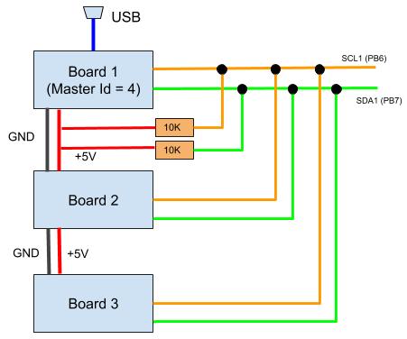
For more boards, it is the same logic. Simply connect SCL1/SDA1 of each board to SCL1/SDA1 bus lines. You do not need more pullup resistors.