Micropython-ESP32 code for custom antennae control based on Ellie Minibot's OC's antennae. WiFi and BLE servers included for control.
Three green LEDs will be controlled by monitoring a connected LiPo battery voltage (not capacity!)
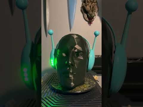
Two LEDs (one on each side) on the antennae bulbs will be PWM controlled in a fading sequence. These can be synced or toggled on/off individually via various control endpoints and services. By default on boot, they will be synced ON.
By default, WiFi Mode is enabled.

-
Download esptool
-
Flash your board
- Replace below command with the appropriate COM# port you plugged in to for the board
./esptool.exe --port COM# erase_flash
-
Flash with MicroPython
- Download latest for ESP32
- Replace COM# with yours below, as well as correct MicroPython binary downloaded
./esptool.exe --chip esp32 --port COM# --baud 460800 write_flash -z 0x1000 .\ESP32_GENERIC-20240602-v1.23.0.bin
I recommend using Thonny
You can easily download the dependencies to the board through it.
- aioble
- Make sure it's the micropython lib
Simply save each of the files in /src/* to the root of the board (do not include the src folder itself). Preserve all filenames
Modify config.json as required. These will be the default settings on every boot.
Note: This file may be written to, but it will only ever change "mode"
See parts folder for details
You can find the files also on Printables
Note: The choice for the "FireBeetle" ESP32 controller was mostly because of the battery plug being on the side and expandability... But the fact it's a "Beetle" is a big bonus I only realized after!
Most of the design from materials, code, and components was chosen to be more accessible and customizable/tinkerable.
{
    "wifi": {
        "name": "minibot_AT", // Access point SSID and hostname (both in AP mode and connected to WiFi)
        "ap_password": "eBot4do8", // Access point Password. Please Change
        "max_connections": 2, // Max number of listeners allowed for the socket control server
        "port": 8080 // Port for accessing the socket control server
    },
    "ble": {
        "name": "minibot_AT", // Bluetooth device name
        "uuid": "6094935a-ba8d-4fbb-9150-904e3244610b", // BLE Service Advertised UUID
        "poll_time": 5 // How often to update BLE read-only sensors
    },
    "mode": 1, // Which mode to boot in.
    "pwm": {  // PWM pins are the Antennae bulbs only.
        "frequency": 500, // Frequency of PWM pins.
        "delay": 0.03, // Delay between fading steps. Min 0.01.
        "off_time_multiplier": 1.2, // Multiplied by delay for time to stay fully off during PWM cycle
        "on_time_multiplier": 4.0, // Multiplied by delay for time to stay fully on during PWM cycle
        "step": 32 // Step count from 0-1024 and 1024-0 for LED brightness in between delays. Min 8
    },
    "leds": { // If true, the LED can be active.
        "green1": true,
        "green2": true,
        "green3": true,
        "left": true,
        "right": true,
        "sync_sides": true
    },
    "poll_time": 2 // Poll time to check for battery voltage in main loop.
}
Mode values:
- 0: None
- No WiFi Socket or BLE Server active. Can only set with direct access to the board and changing the config on-board.
- 1: WiFi
- Enables WiFi. Will create an AP to connect to and configure a 2.4Ghz WiFi to connect to and save details for.
- When successfully connected to a WiFi, will create a socket server at the specified port
- 2: BLE
- Enables the BLE server
If you can't find the IP address, it will have the hostname configured as "name" in the "wifi" section of the configuration. By default, this will mean it has a hostname of minibot_AT, may work as minibot_AT.local.
When in AP mode to setup a network connection, hostname should work but if not, the setup page usually will be available at 192.168.4.1 when connected to it.
If setting up multiple, please change the hostname and maybe the password for security.
If you don't have a second device to setup wifi with, you can manually setup WiFi connection via a file
In the root of the board, create a wifi.dat file and on the first line put in SSID_NAME;SSID_PASSWORD then add a blank empty newline after it
It must be a 2.4ghz SSID. Also for setting up multiple, you can do a new one on each line.
- GET
- /, /data
- Returns JSON with battery_voltage and uptime_s
- Example
{"battery_voltage": 4.135, "uptime_s": 155.984}
- Example
- Returns JSON with battery_voltage and uptime_s
- /restart
- Hard-restart the board
- /mode/1
- Tells you that you're dumb cause you're already in WiFi Mode
- /mode/2
- Switch to BLE and restart board
- /leds/right/off
- Turn OFF Right Antenna LED
- /leds/right/on
- Turn ON Right Antenna LED
- /leds/left/off
- Turn OFF Left Antenna LED
- /leds/left/on
- Turn ON Left Antenna LED
- /leds/sync/off
- Turn OFF Antenna LEDs (Sync)
- /leds/sync/on
- Turn ON Antenna LEDs (Sync)
- All other endpoints result in HTTP 404. All previous in HTTP 200
- /leds?delay=####
- Set the PWM Delay to this value in seconds. Accepts floats. E.G.,
?delay=1= 1s,?delay=0.02= 200ms - Can pass in
delay=default - Min value = 0.012, Max value = 10, default 0.03 (without modification)
- Set the PWM Delay to this value in seconds. Accepts floats. E.G.,
- /leds?steps=####
- Set the PWM Steps to this whole number value. E.G.,
?steps=32,?delay=0.03&steps=32 - Can pass in
steps=default - Min value = 8, Max value = 128, default 32 (without modification)
- Set the PWM Steps to this whole number value. E.G.,
- /, /data
- Battery Voltage: 0x2BF0
- Uptime Sensor (Seconds): 0x183F
- Switch Modes: 0x04C3
- 1 uint8: Switch to WiFi and restart board
- All other inputs ignored
- LED Control: 0x77DA
- 0 uint8 - Turn OFF Left Antenna LED
- 1 uint8 - Turn ON Left Antenna LED
- 2 uint8 - Turn OFF Right Antenna LED
- 3 uint8 - Turn ON Right Antenna LED
- 4 uint8 - Turn OFF Antenna LEDs (Sync)
- 5 uint8 - Turn ON Antenna LEDs (Sync)
- All other inputs ignored
- Set PWM Delay: 0x77DB
- Milliseconds uint16 big endian - Set PWM Delay, accepts milliseconds, not seconds.
- Value of 0 will set it to the default of 0.03
- Set PWM Steps: 0x77DC
- Steps uint8 - Set the PWM Steps, accepts whole numbers from 0 to 128
- Value of 0 will set it to default of 32.
You can remotely configure the PWM parameters for the bulb LEDs with WiFi or BLE. Delay will update as soon as the old delay time has elapsed so near-instant. Step will update only after a step up or step down cycle has completed for an up-cycle or down-cycle.
For example, you can adjust the delay (and steps value, but delay is preferred) remotely based on other values. One use case may be to sync entering/exiting ranges of a heart rate monitor's BPM to push different delay values, or perhaps rate ranges of any other activity.
Examples for WiFi control of PWM adjustments:
- For a really fast cycle, I recommend
?delay=0.012&steps=64or?delay=0.012&steps=128(fastest) - Default would be
?delay=0.03&steps=32or?delay=default&steps=default
The green LEDs are not controllable as they work as battery indicators. Rather than measure current or capacity which would be more accurate, I did not have time to plot the graph to tell capacity at specific voltages as it will be battery dependant, so it is at arbitrary battery voltage amounts. A 3.7v lipo at full charge is near 5v, and will stay around 4.2v for a very long time, and when there is approx 10% and 20% ish or less remaining it will turn off the top led's. It may shut down all processing and threads shortly after reaching single-LED mode if there is not enough power left (roughly when it gets to 3.2v or below, and will full stop at under 3v).
When there is only the last LED left one, it is possible the board will go into a deep sleep and stop all threads (no WiFi, BLE, or PWM Fades). In this mode it will keep that last LED lit for approximately 2 hours.
ALL values are reset to default when the board is restarted or switching modes. Only the value of the mode is retained after restarting, and is written to the config file.
If for whatever reason it is stuck and not connecting to WiFi or threads got stuck like from being in deepsleep and back up again after charging, just quickly disconnect the pogo connectors when it's not charging for a second. This also acts as the power switch - there is none, just unplug one side of the pogo wire.
When enabling an individual LED while Sync is on, it will disable Sync and the other LED will need to be turned on separately if you want both unsynced. Turning off Sync when sync is not enabled will do nothing. Turning on Sync will restart both lights.
When using the 1100maH battery, it will last roughly 17 hours on a full charge (charging ~1h at 2A), but can last easily 11-13 hours on fullish charge (~20-30min at 2A). Battery capacity is not measured but rather voltage levels are used as ranges to signal the three green LEDs. Just because all are lit up does not mean it is fully charged by far.