This is CSE211 GPS tracking system project using Ti's Tiva TM4C board with ARM Cortex-M microcontroller.
| Program | Name | ID |
|---|---|---|
| CSE | Ali Mohsen Yehia Ateya | 2000289 |
| ECE | Amr Samir Fikry Ibrahim | 2000987 |
| ECE | Mohamed Magdy Mohamed Amin | 2001986 |
| ECE | Youssef Emad Eldin AbdelAzem | 2001429 |
| CSE | Adham Khaled Abdelmaqsoud Ali | 2000066 |
| ECE | George Nabil Henry | 2000086 |
| ECE | Omar Hesham Abdelhaseeb Mohamed | 2001015 |
- The GPS system stores the coordinates of the start point.
- After reaching the destination point, the GPS system stores the coordinates of the end point and calculates the total distance that was taken by the user.
- The output will be translated as the following.
- The built-in LED will be turned on(green) when the target destination is reached.
- The built-in LED will be turned on(yellow) when the target destination is about to be reached < 5 meters.
- The built-in LED will be turned on(red) when the target destination is far away by distance > 5 meters.
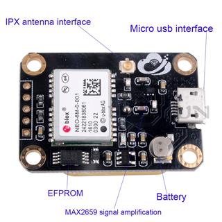
- We get the info about our position from the GPS satalites through an antenna.
- Then the GPS module takes this info and determines the position through some calculations.
- Then the GPS module sends this processed info about the position every one second in the form of NMEA sentences.
- The GPS module is connected to tm4c board through serial UART commuincation and inputs the NMEA sentences to the board.
- We recieve the NMEA sentences to the board and extract the coordinates info from it.
- Then we use the current coordinates to determine the distance to the destination and decide which led color to turn on.
- Also the program computes the total distance traveled by summing the distances between each two positions every second.
- Finally the program prints the total distace traveled on the serial monitor through UART0 on computer program (PuTTY).
- First we connect Vcc and gnd on GPS module and Tiva board together.
- Then we connect Rx of GPS module with Tx of Tiva board and vice versa.
- Since we will use UART1 for GPS we will connect Rx and Tx of GPS module with PB1 and PB0 respectively.
Three initialization functions of the ports A, B and F.
- initPortA
- initPortB
- initPortF
Two initialization functions of UART0 and UART1.
- initUART0
- initUART1
A function to write a single character on UART0.
- write_UART0
Three print functions on UART0 (serial monitor) that uses write_UART0.
- printString
- printStringln
- printDouble
A function to read a single character from UART1.
- read_UART1
A function that creates the string taken from UART1 (GPS) using read_UART1.
- makeInputString
A functions to extract the coordinates from the NMEA sentence.
- getCoordinates
A function to convert coordinates to degrees.
- fixCoordinate
In systick.c:
A function to initialize Systick.
- initSystick
Two functions to make delay in seconds and milli seconds.
- delayInSeconds
- delay
In main_functions.c:
Two Functions used in main to make it more readable.
- chooseLedColor
- calculateStepsTaken
A function to calculate distacne between two points.
- distance
Two functions to turn on/off the leds
- ledON
- ledOFF


