Arduino control of a Sony camera with Multiport support.
This implementation uses the broken out connector from this vendor: https://www.studio1productions.com/sony-multiport-connector.htm
Alternate vendor: https://www.aliexpress.us/item/3256802869633950.html?gatewayAdapt=glo2usa4itemAdapt&_randl_shipto=US
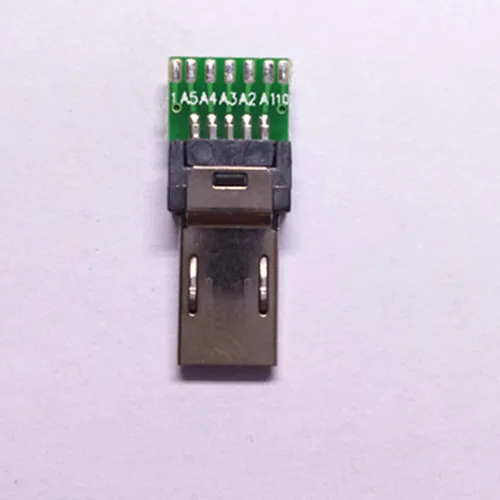
In order to control camera power on/off and the shutter function, pins labled 1, 2, 4, & 5 are used. The description of each pin is shown at the bottom of this post.
To control your camera with an Arduino, wire up the following schematic:
- 2N2222 BJT transistors are used as digital switches to protect the internal hardware of the camera.

Make the following connections:
- Connect CAM_Shutter to pin 4 of the Multiport connector
- Connect CAM_Focus to pin 5 of the Multiport connector
- Connect CAM_Power to pin 2 of the Multiport connector
- Connect GND to pin 1 of the Multiport connector and the ground pin of your Arduino
- Connect GPIO_Power, GPIO_Focus, and GPIO_Shutter to digital pins of your Arduino.
In Software:
-
Drive GPIO_Power high to toggle camera power.
-
Drive GPIO_Focus high, delay for a few milliseconds, then drive GPIO_Shutter high in order to capture an image.
- Both focus (pin 5) and shutter (pin 4) pins must be shorted to ground in order for the camera to take an image.
PIN DESCRIPTIONS from: https://www.studio1productions.com/sony-multiport-connector.htm
| Pin | Usage |
|---|---|
| A1 | VBUS (5 volt, max 2A) |
| A2 | USB D-1 |
| A3 | USB D+1 |
| A4 | USB ID |
| A5 | Ground |
| 1 | Power On / Off - Short to Ground to toggle between Power On or Off. |
| 2 | Ground |
| 3 | Composite Video Out - Not supported when using a wired remote control unit |
| 4 | Audio Out L / Shutter Release - Shutter with direct trigger cable. Note: Audio is not supported when using a wired remote control unit |
| 5 | Audio Out R Audio / Activate Camera / Focus - Focus with direct trigger cable. Note: Audio is not supported when using a wired remote control unit |
| 6 | Select - resistor to detect the connected cable or accessory type. Resistor to Pin 2 or Pin 10 depending on accessory type or cable. Use 100 ohm Resistor. |
| 7 | UART RX / Boot Serial In - optional input for serial interface (debug) and boot loader. No Boot Loader. |
| 8 | UART TX / LANC Sig - optional output for serial LANC interface for debug / No LANC control |
| 9 | XReset Req / Input for reset request |
| 10 | 2.8 volt to 3.3 volt output |