-
Notifications
You must be signed in to change notification settings - Fork 11
Home
The idea to build standardized approach of sensor-box hub emerged while building home automation system. I needed to connect many devices over MQTT to some control system. I used Cayenne platform and mix of devices - Arduino, ESP8266, RPI. After I managed to connect ventilation system, power meters, temperature logging, air quality monitors I quickly discovered that it is not the way to go. Each time I needed a breadboard, wires, modules and custom enclosure. So I decided to re-make the approach that I developed years ago. At that time I wanted to have everything in one box with ability to connect several sensors, with auto-detection, as well as various communication channels - WiFi, GPRS, Ethernet, 433MHz. Plus various power supplies including DC, PoE, 230V AC. Plus multiple user interfaces including LCD, keyboard, extension connector.
The device became very costly and too complex for some simple tasks. So let's reinvent it. Features I'd like to have:
- low cost, well below 20$ per module
- modular approach to be able to serve both simple and complex approaches
- really tiny - want to pack it to constrained area like crowded fuse box in my house
- ability to read many sensors like: humidity, temperature, power meter, air quality, distance, AC voltage, MODBUS
- ability to control devices like: relays, PWM, voltage, MODBUS, CAN
- automatic configuration - connection of a sensor or transducer causes automatic update of mobile app and web interface.
- compatibility with web service via MQTT protocol.
- usage of existing web and mobile app software.
- Wifi, Ethernet and BT interfaces. I don't trust WiFi. For many critical applications Ethernet cable is a must.
- Optional GPRS connectivity
- LoRa connectivity
- single CPU approach - lack of inter-cpu communication, single software to maintain
- low power consumption. RPI-grade device power consumption is far too much. Single device is OK, but if you install them in tens of places it becomes an overkill cause the system that was meant to save power consumes more than is able to save.
- configuration via webpage or app
- supply via POE,DC, USB or battery
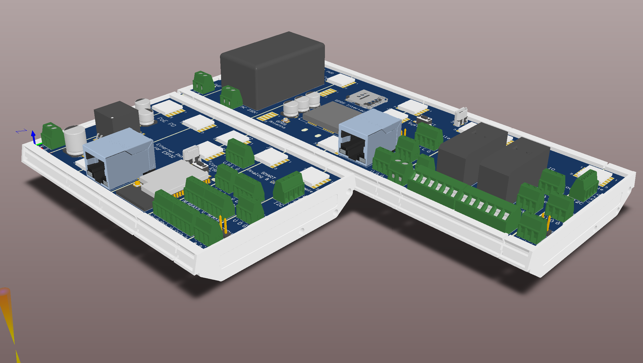
Below is a drawing of the modular system I designed. It is still in development process but critical parts were verified using Arduino-style modules or breadboards or reused from other working designs. Several aspects and design choices were described in the issues. Two example configurations are shown below:

The HW has just arrived
| Board name | HW status | SW status | Next activity |
|---|---|---|---|
| ESP32 base module | assembled in various configurations and tested, schematics done | Cayenne running | PCB routing |
| Ethernet PHY for ESP32 base module | verified on devkit, schematics done | verified connectivity | PCB routing |
| Arduno M0 compatible base module with Ethernet , 1-Wire and RS485 | verified on Arduino M0 and RS485 module, schematics done | Cayenne running | PCB routing |
| PoE for Ethernet PHY | verified in HW, schematics done | no SW | PCB routing |
| Single channel power meter that can be extended to any number of channels | verified in HW, schematics done | Cayenne running | PCB routing |
| GPRS connectivity | partially verified, schematics done | PCB routing | |
| AC power input module | schematics done | no SW | PCB routing |
| DC power input module | verified in HW, schematics done | no SW | PCB routing |
| Relay and analog IO module | schematics done | PCB routing | |
| Simple IO module with I2C, RS485 and 1-WIRE as extension for ESP32 module | schematics done | no SW | PCB routing |
| Smart IO module with I2C, 1-Wire, analog inputs, analog outputs, digital inputs, digital outputs | schematics done | PCB routing | |
| Smart CAN module supporting wall light switch | verified with Arduino ProMicro and CAN adaper board, schematics done | hapcanuino running | PCB routing |
| Linux Hub module | Orange Pi module arrived, schematics done | PCB routing | |
| Backup LiOn module | verified in HW | no SW | schematics |
| LoRa base module | modules and router arrived | schematics | |
| Air quality Sensor module | PMS and VOC verified in HW, schematics done | working with Cayenne | PCB routing |
| RGB LED Driver module | Schematics done | PCB design |
- LCD module
- Humidity, temperature and pressure sensors module, at the moment they can be connected to general purpose IO modules.
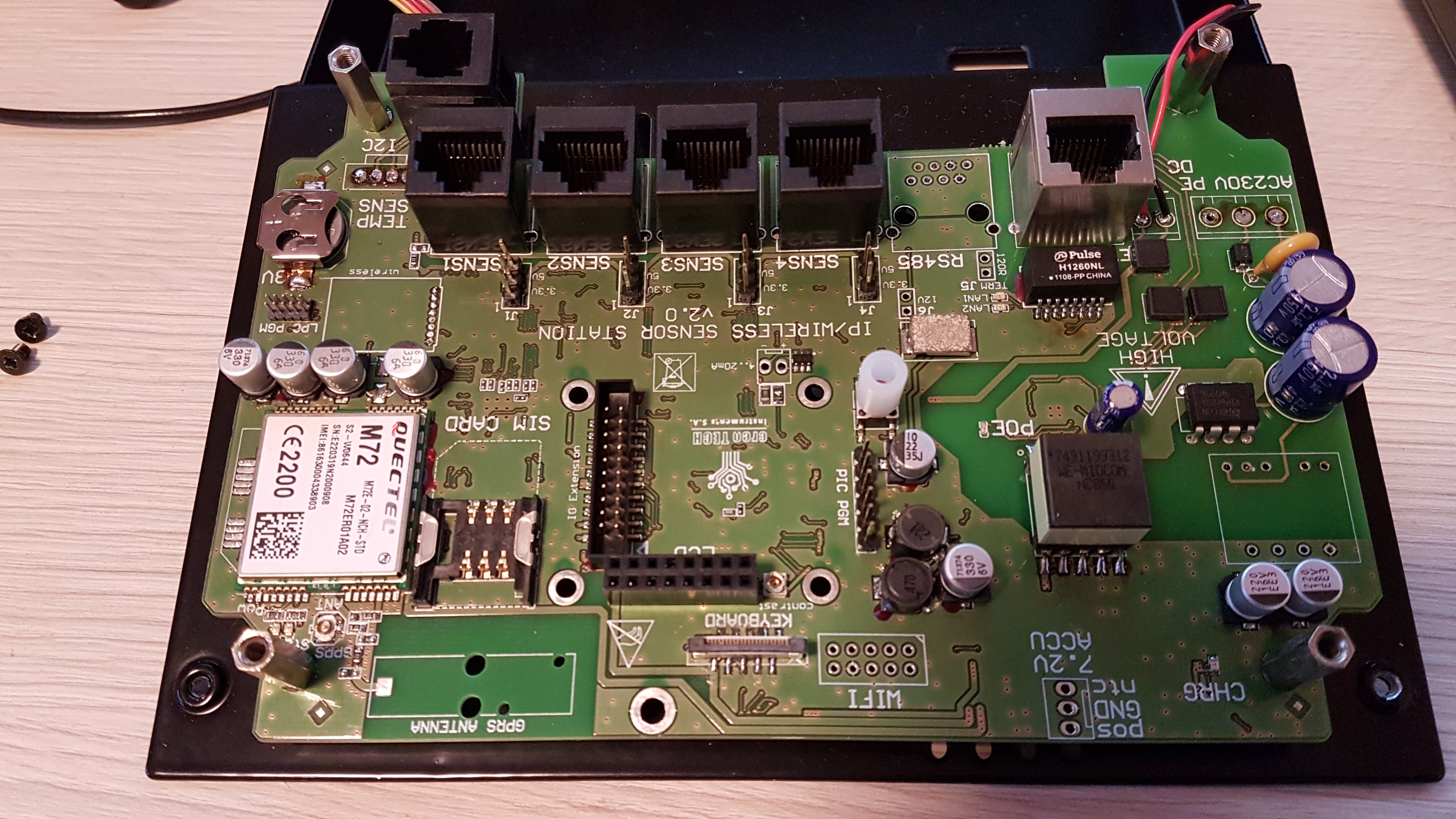
Here is the device described at the beginning of the Wiki.

However very first version was meant to be portable and it was master thesis of my student - here is the project and the documentaiton
Then I needed multichannel temperature logger with Ethernet access. So I used 16 low cost KTY18 sensors with AFE based on general purpose opamps + 10 bit ADC + embedded Linux single-board computer. The sensors required time-consuming calibration and I was not happy with such approach. The sensors were cheap but needed lots of work prior using them.
Some render...
Yet another device was built as a Bachelor thesis of my student, Michal Krzeminski. It was portable temperature logger that cooperates with any type of resistive sensors. It supports up to 15 channels. Results are logged to the SD card. Initial application was temperature tests of enclosed PCB where miniature PT100 sensors were used.
Altium sources of the devices described above are here
