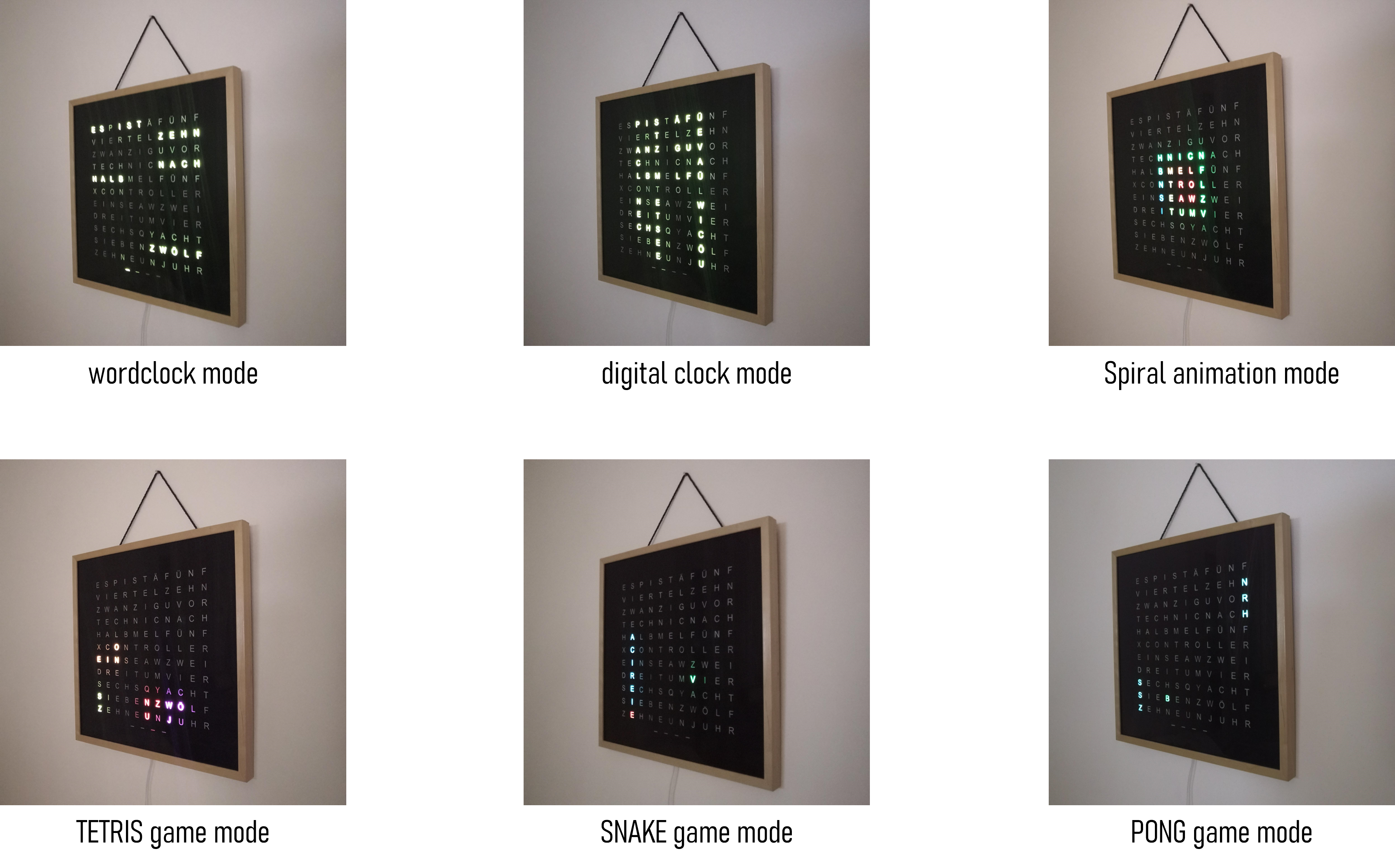
I taught the excellent word clock from techniccontroller some Luxembourgish. So this version has a different front plate, grid and an other "start message", as well as the corresponding software changes. The installation process is the same, so I included the authors description in this readme (down there!)
You can find the stl files for the front plate and the letter seperating grid (to avoid light leakage) also in this repo. print it with black PETG (maybe PLA also does the job). Other colors might not keep the light just on one letter.
I followed loosely the tutorial from techniccontroller when assembling the hardware.
My wordclock uses
-
as base a 23 cm x 23 cm wooden 3d frame like this one
-
diffusion foil (has to be at least frame size) like this one
-
WS2812B addressable LED stripes 3m, 60 LEDS/m like this one
-
and this ESP case on the back
I did not include an on-off-switch in my version and I power it directly from the ESP. If you are unsure with that, you can include the USB socket like in the original tutorial. The material, I used same as in the original tutorial were: ESP8266 from AZDelivery, USB power supply 5V/3A, 470 Ohm resistor, 1000uF capacitor, micro USB cable, some cables
- I started by 3d printing the Front plate so I could use it, to positionate the LEDs to glue them on the back plate of the frame. For that i used dark eye shadow to trace through the letters on the plate:
- Then I glued the LEDs strips and connected them following the original tutorial. Keep in mind, that you need 11 LEDs per row and 12 rows (that is different) plus the for LED row at the bottom.
-
The connection between the LEDs and to the ESP is also nearly the same as in the original tutorial, I did not include the switch and the additional usb socket. So I connected the LED strips to the VU/5V and the GRD Pin of the ESP.
-
I glued the esp in the printed case from thingiverse at the back of the back plate.
-
To bring it all together: place the printed grip on the plate, so that every letter is in one of the cells. then you put the diffusor foil on it. Then you put the printed front plate on that. (Ignore the wrong printed grip on top of the image)
- You can cut the passepartout of the frame, so it shows all of the letters. Fixate the front plate in the back with some tesa or glue of your gusto. Put it into the frame and - Taaadaaa - your Word Clock is ready.
In difference to the original it says "ech hunn dech gär" when starting (it was a present for a beloved one ;-)), you can change that back in wordclock_esp8266.ino, by commenting lines 361 - 379 out and decomment lines 381 - 387. It will show its ip adress instead.
Original description from techniccontroller
Wordclock 2.0 with ESP8266 and NTP time
More details on my website: https://techniccontroller.com/word-clock-with-wifi-and-neopixel/
Languages
The Wordclock is available in German, English and Italian language. By default the language is German. To use the English or Italian language please replace the file wordclockfunctions.ino with wordclockfunctions.ino_english or wordclockfunctions.ino_italian. The code compiles only with one file named wordclockfunctions.ino. So please rename the file you want to use to wordclockfunctions.ino and replace the existing file.
- 6 modes (Clock, Digital Clock, SPIRAL animation, TETRIS, SNAKE, PONG)
- time update via NTP server
- automatic summer/wintertime change
- easy WIFI setup with WifiManager
- configurable color
- configurable night mode (start and end time)
- configurable brightness
- automatic mode change
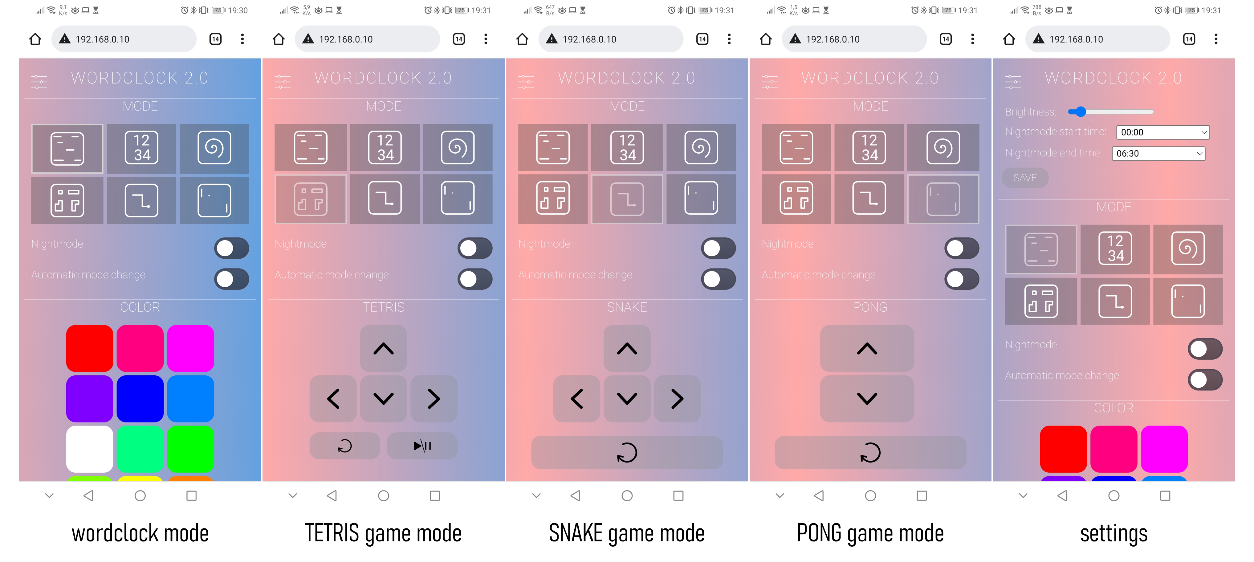
- webserver interface for configuration and control
- physical button to change mode or enable night mode without webserver
- automatic current limiting of LEDs
- Clone the project into the sketch folder of the Arduino IDE,
- Rename the file "example_secrets.h" to "secrets.h". You don't need to change anything in the file if you want to use the normal WiFi setup with WiFiManager (see section "Remark about the WiFi setup").
- Install the additional libraries and upload the program to the ESP8266 as usual (See section Upload program to ESP8266 below).
- The implemented WiFiManager helps you to set up a WiFi connection with your home WiFi -> on the first startup it will create a WiFi access point named "WordclockAP". Connect your phone to this access point and follow the steps which will be shown to you.
- After a successful WiFi setup, open the browser and enter the IP address of your ESP8266 to access the interface of the webserver.
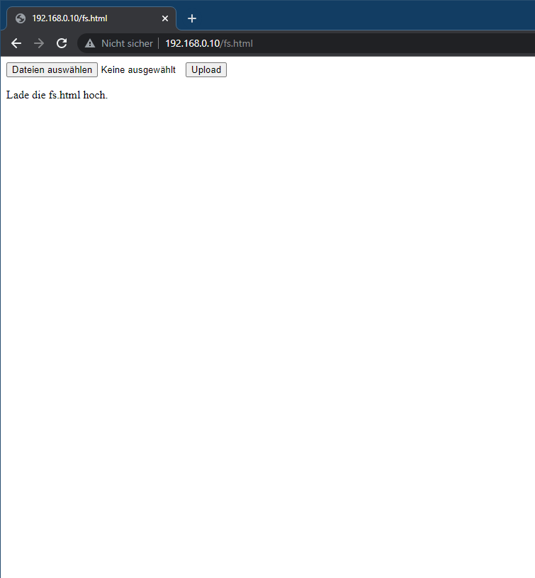
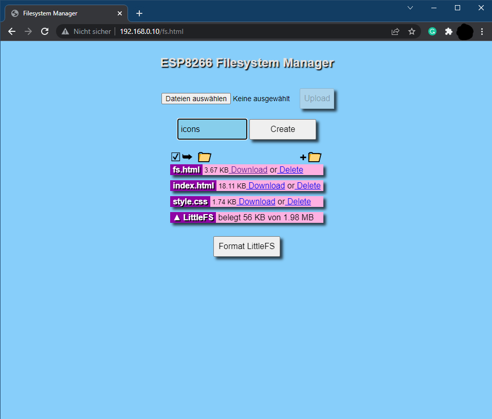
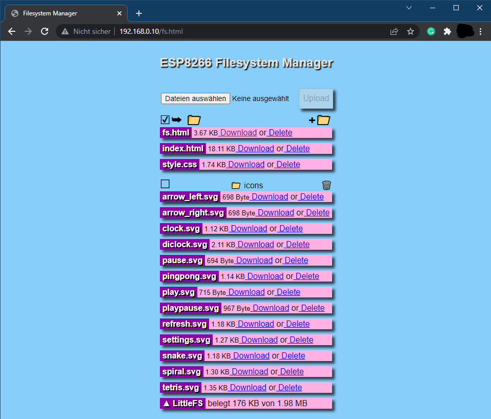
- Here you can upload all files located in the folder "data". Please make sure all icons stay in the folder "icons" also on the webserver.
Please download all these libraries as ZIP from GitHub, and extract them in the libraries folder of your Sketchbook location (see File -> Preferences):
- https://github.com/adafruit/Adafruit-GFX-Library
- https://github.com/adafruit/Adafruit_NeoMatrix
- https://github.com/adafruit/Adafruit_NeoPixel
- https://github.com/tzapu/WiFiManager
- https://github.com/adafruit/Adafruit_BusIO
folder structure should look like this:
MySketchbookLocation
│
└───libraries
│   └───Adafruit-GFX-Library
│   └───Adafruit_NeoMatrix
│   └───Adafruit_NeoPixel
│   └───WiFiManager
│   └───Adafruit_BusIO
│
└───wordclock_esp8266
    │   wordclock_esp8266.ino
    │   (...)
    |
    └───data
        │   index.html
        |   (...)
        |
        └───icons
First, the latest version of the Arduino IDE needs to be downloaded and installed from here.
To program the ESP8266 with the Arduino IDE, you need to install the board information first in Arduino IDE. To do that follow the following instructions:
-
Start Arduino and open the File -> Preferences window.
-
Enter http://arduino.esp8266.com/stable/package_esp8266com_index.json into the Additional Board Manager URLs field. You can add multiple URLs, separating them with commas.

-
Open Boards Manager from Tools > Board menu and search for "esp8266".
-
Click the install button.
-
Don’t forget to select your ESP8266 board from Tools > Board menu after installation (e.g NodeMCU 1.0)

- Open wordclock_esp8266.ino in Arduino IDE
- Connect ESP8266 board with Computer
- Select right serial Port in Tools -> Port
- Click on the upload button in the Arduino IDE to upload the program to the ESP8266 Module.

Regarding the WiFi setting, I have actually implemented two variants:
- By default the WifiManager is activated. That is, the word clock makes the first time its own WiFi (should be called "WordclockAP"). There you connect from a cell phone to
192.168.4.1* and you can perform the configuration of the WiFi settings conveniently as with a SmartHome devices (Very elegant 😊) - Another (traditional) variant is to define the wifi credentials in the code (in secrets.h).
- For this you have to comment out lines 230 to 251 in the code of the file wordclock_esp8266.ino (add /* before and */ after)
- and comment out lines 257 to 305 (remove /* and */) (* default IP provided by the WifiMAnager library.)
You can clear the stored WiFi credentials and restart the WiFi setup described above with these steps:
- Open the settings panel in the web UI.
- Enable 'Reset WiFi' slider.
- Save settings.
- LED test should be performed.
- Disconnect and reconnect the power. WiFi credentials were removed. The setup should be restarted. Resetting the wifi credentials does not delete uploaded files.
The wordclock sends continuous log messages to the serial port and via multicast UDP. If you want to see these messages, you have to
- open the serial monitor in the Arduino IDE (Tools -> Serial Monitor). The serial monitor must be set to 115200 baud.
OR
- run the following steps for the multicast UDP logging:
- Starting situation: wordclock is connected to WLAN, a computer with installed Python (https://www.python.org/downloads/) is in the same local area network (WLAN or LAN doesn't matter).
- Open the file multicastUDP_receiver.py in a text editor and in line 81 enter the IP address of the computer (not the wordclock!).
# ip address of network interface
MCAST_IF_IP = '192.168.0.7'- Execute the script with following command:
python multicastUDP_receiver_analyzer.py-
Now you should see the log messages of the word clock (every 5 seconds a heartbeat message and the currently displayed time). If this is not the case, there could be a problem with the network settings of the computer, then recording is unfortunately not possible.
-
If special events (failed NTP update, reboot) occur, a section of the log is saved in a file called log.txt. In principle, the events are not critical and will occur from time to time, but should not be too frequent.


