-
Notifications
You must be signed in to change notification settings - Fork 5
Electronics
This configuration supports direct software control of up to 4 laser lines and uses 8 AO (analog output) and 8 DO (digital output) lines total, generated by the NI PXI-6733 card.
| Channel | Purpose | Notes |
|---|---|---|
| ao0:3 ('PXI1Slot4/ao0:3') | galvo-L, galvo-R, ETL-L, ETL-R connection. | The BNC cables from AO0, AO1, AO2, AO3 terminals must be connected to galvo-L, galvo-R, ETL-L, ETL-R controllers |
| ao4:7 ('PXI1Slot4/ao4:7') | laser1:4 intensity control | Different laser combiners use different maximum voltage (1, 5, or 10 V). Check the laser datasheet and modify the config file accordingly. |
| do0 ('PXI1Slot4/port0/line0') | master pulse | Digital line that generates the master pulse 'PXI1Slot4/port0/line0' must be connected to PFI0 BNC terminal of the BNC block by a wire. |
| do1 ('/PXI1Slot4/ctr0') | camera trigger | BNC cable from PFI12 / P2.4 ('/PXI1Slot4/ctr0') connects to camera's Trig_IN terminal. |
| do2 ('/PXI1Slot4/ctr1') | stage trigger | BNC cable from PFI13 / P2.5 ('/PXI1Slot4/ctr1') connects to ASI Tiger Trig_IN terminal. |
| do3 ('/PXI1Slot4/port0/line1') | left/right arm illumination | Switching between two fibers is performed by the laser combiner (dual-output model). The digital output '/PXI1Slot4/port0/line1' is connected to the laser combiner input terminal. |
| do4:7 ('PXI1Slot4/port0/line2:5) | laser ENABLE | Digital ON/OFF switching of the lasers. Shutter is not required because lasers can be completely turned off with the ENABLE digital signals. |
Update: As Tchern Lenn pointed out, physical connection from P0.0 to PFI0 is optional and can be done in the config file instead. This releases one digital channel (relevant on some NI cards), and saves wiring time.
The National Instruments (NI) devices are used for generation of analog and digital signals that control the system.
- Acquisition workstation (Windows 10, x64)
- Latest DAQmx drivers installed.
- NI PXIe-1073 Chassis
- NI PCIe-8361 interface card
- NI PXI-6733 analog output module
- NI BNC-2110 connector block
- SH68-68-EPM Shielded Cable, 68 D-Type to 68 D-Type
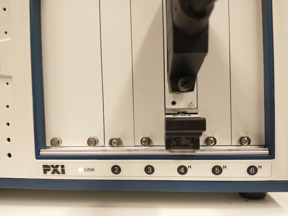
- Insert PXI-6733 module into slot of PXIe-1073.

TODO: Photo of all things connected
- Insert the PCIe-8361 card into a free slot of your workstation motheboard.
-
Connect the PXIe-1073 chassis to the PCIe-8361 inserted in workstation using the cable provided.
-
Connect the BNC-2110 block to the PXI-6733 module using the SH68-68-EPM cable.
-
Power up the PXIe-1073 chassis, then the workstation.
-
Open NI MAX software and check Devices. You should see PXIe-1073 chassis and the PXI-6733 in the drop-down menu.
-
In necessary, change the label of the PXI-6733 module by double-clicking on its label field. This name will be used in the mesoSPIM/config/my_config.py file of mesoSPIM control software.
TODO: Screenshot of NI MAX
The NI PXI chassis allow modular extensions of the system. If you need to control 5-8 lasers in your system, you should add the following NI components to your system:
| NI part number | Name | Qty | Purpose |
|---|---|---|---|
| 779632-01 | PXI-6259 (32 Analog Inputs, 48 Digital I/O, 4 Analog Outputs) | 1 | Control of galvos, ETLs, and trigger tasks |
| 192061-01 | SHC68-68-EPM Shielded cable, 1m | 2 | To connector blocks |
| 777643-01 | BNC-2110 Noise Rejecting, Shielded BNC Connector Block | 2 | Connector blocks |
(total cost about 5600 EUR in 2024)
The PXI-6733 card, used for controlling all signals in 4-laser configuration, becomes dedicated to control lasers only, similar to configuration of original mesoSPIM-v5
- PXI-6259 card name:
PXI1Slot4 - PXI-6733 card name:
PXI1Slot5
| Channel | Purpose | Notes |
|---|---|---|
| ao0:3 ('PXI1Slot4/ao0:3') | galvo-L, galvo-R, ETL-L, ETL-R connection. | The BNC cables from AO0, AO1, AO2, AO3 terminals must be connected to galvo-L, galvo-R, ETL-L, ETL-R controllers |
| do0 ('PXI1Slot4/port0/line0') | master pulse | Digital line that generates the master pulse 'PXI1Slot4/port0/line0' must be connected to PFI0 BNC terminal of the BNC block by a wire. |
| do1 ('/PXI1Slot4/ctr0') | camera trigger | BNC cable from PFI12 / P2.4 ('/PXI1Slot4/ctr0') connects to camera's Trig_IN terminal. |
| do2 ('/PXI1Slot4/ctr1') | stage trigger | BNC cable from PFI13 / P2.5 ('/PXI1Slot4/ctr1') connects to ASI Tiger Trig_IN terminal. |
| do3 ('/PXI1Slot4/port0/line1') | left/right arm illumination | Switching between two fibers is performed by the laser combiner (dual-output model). The digital output '/PXI1Slot4/port0/line1' is connected to the laser combiner input terminal. |
| ao0:7 ('PXI1Slot5/ao0:7') | laser1:8 intensity control | Different laser combiners use different maximum voltage (1, 5, or 10 V). Check the laser datasheet and modify the config file accordingly. |
| do0:7 ('PXI1Slot5/port0/line0:7) | laser ENABLE | Digital ON/OFF switching of the lasers. Shutter is not required because lasers can be completely turned off with the ENABLE digital signals. |
The config.py file must be adapted accordingly, see mesoSPIM-v5 instructions.
This is a lower-cost option suggested by Tchern Lenn from UCL. It uses single NI PXIe-6738 card that features 32 analog output channels but only 10 digital I/O channels, so a bit different configuration and connector block are required. Check the details at the dedicated folder benchtop/Benchtop-UCL-London.
- Overview
- Room requirements
- Safety
- Parts list
-
Assembly
- Overview
- Detection arm
- Excitation arms
- Sample stages
- Electronics
- Lasers
- Immersion chambers (TODO)
- Front cover (with webcam)
- Enclosure (TODO)
- Usage
- Troubleshooting and typical errors (TODO)
- Maintenance(TODO)
- Technical notes