![]()
Design RC plane wings and generate G-Code for a 4-axis CNC foam cutter.
Hotwing dash provides an web-based editor (with auto-completes) to author the config and visualize the Gcode generated by hotwing-cli and hotwing-core library.
The project mostly uses hotwing-core library, with:
- alternative cutting strategy - trailing edge first
- all hotwing-cli command line options now part of config
- additional config options (see Gcode section below)
- visualization using Plotly
- website using Dash
pip install -r requirements.txt
Dash runs on top of a Flask container, it can be run from command line:
python hotwing_dash.py
Or more production setup using Heroku, Elastic Bean Stalk or roll your own using uWSGI, gunicorn and nginx
Short demo clip hosted on youtube:
Two wings JW36's cut using Hotwing Dash

To define the configuration of a wing, either select "new" or "upload" from the Generate tab. Suggest starting with "new" to get a sense of the options available.
The config editor is implemeted using dash-ace and supports:
- autocompletion of parameters, values
- math expressions using numexpr
In order to explain the various options, this alternative Wiesel wing design from https://www.rcgroups.com/forums/showthread.php?1456458-Wisel-just-the-glider-you-need is used:

The wingspan is 900mm, the root chord is 330mm and the tip chord is 180mm. In HotWing we work with wing halves, so let's see what that looks like.

For this project we we'll be working in inches, so in the Project section we will specify the units.
[Project]
Name = Example Config
Units = millimeters
...
Name - Used to generate the config filename when downloading ("Example Config.txt") and the filename for gcode ("Example Config.gcode").
Units - Defines the project to be in 'inches' or 'millimeters'. Default is inches if not specified.
According to the wing plan the profile is a PW-1211, a quick Google search finds it here http://airfoiltools.com/airfoil/details?airfoil=pw1211-pw :

This is a very useful site - note at the bottom righthand side are links for both Selig and Lednicer coordinate files (both supported by Hotwing).
...
[RootChord]
Profile = http://airfoiltools.com/airfoil/seligdatfile?airfoil=pw1211-pw
Width = 330
LeadingEdgeOffset = 0
Rotation = 0
RotationPosition = 0.5
...
Profile - The profile is a URL to the airfoil coordinates. The software accepts Selig and Lednicer type coordinates files
ProfileThickness - Thickness as percentage (optional). For example 10, means the profile thickness is scaled to be max 10% of the chord.
For example - profile at 3% (ProfileThickness = 3)

vs
profile at 6% (ProfileThickness = 6)

Width - We know the width from the design above is 330mm at the root.
LeadingEdgeOffset - We want the tip of the airfoil to be at 0 - I.E. we don't want to move it.
Rotation - Leave this at 0. I don't want to rotate this chord.
RotationPosition - This doesn't matter since the Rotation Parameter is 0.
Now let's modify the tip chord. Similar to the Root but let's take a look at some of the other Parameters.
...
[TipChord]
Profile = http://airfoiltools.com/airfoil/seligdatfile?airfoil=pw1211-pw
Width = 180
LeadingEdgeOffset = 100
Rotation = -1
RotationPosition = 0.25
...
LeadingEdgeOffset - To get the shape that we want we need to define the LeadingEdgeOffset. If we don't define the LeadingEdgeOffset, the leading edge's will be straignt and the trailing edge will sweep forward like this:

From the wing plan, the LE-sweep is 100mm - in Hotwing terms this is the LeadingEdgeOffset:

Rotation - For this design we need 1 degree of washout on the tip, so I need to set the Rotation Parameter to -1. This will angle the tip downward by 1 degree. To angle the tip upward, use a positive number.
RotationPosition - Since the Rotation value is now being used, the RotationPosition will be taken into account. This value is the point along the chord (measured from front to back) where the foil will be rotated. A value of 0.25 tells HotWing to rotate the foil around a point at 25% of the chord distance. Since our chord is 180mm long, the rotation will occur 45mm (25%*180) back from the tip of the foil.
...
[Wing]
TipChordSide = right
Width = 450
Inverted = no
VerticalAlignProfiles = dihedral
Dihedral = 1

StockLeadingEdge = 0
StockTrailingEdge = 20
StockTrailingEdgeAngle = 45

SheetingTop = 0.0
SheetingBottom = 0.0
...
TipChordSide - [New] Determines if we are cutting the left hand wing (TipChordSide = left) or the right hand wing (TipChordSide = right). In hotwing-cli this is a command line option. Valid options are "left" and "right".
Width - The total width of the half wing.
Inverted - [New] Should the wing be inverted - useful for cutting left and right hand wings on the same side of the foam cutter
VerticalAlignProfiles - Used in the case when VerticalOffsetTip is omitted. Three options are available "default", "bottom" and "dihedral". "default" aligns the chords of the Tip and Root profile. "bottom" aligns the lowest points. "dihedral" uses the Dihedral property to determine the offset
For example the following two figures shows default alignment:

and bottom alignment:

Dihedral - sets the dihedral in degrees - ignored if VerticalAlignProfiles is not set to "diheral"
StockTrailingEdge - Useful for trimming the wing for ailerons or elevons as shown in the following example, with StockTrailingEdge=40. After cutting the wing the wire moves to SafeHeight, moves horizontally over the foam and performs a vertical cut at the specified distance from the leading edge:

StockTrailingEdgeAngle - (Experimental) Angle at which to trim the trailing edge, useful when using square balsa control surfaces to get a precise hinge

StockLeadingEdge - Similar to the trailing edge, the leading edge can also be trimmed
SheetingTop and SheetingBottom - The next parameters that need to be set are SheetingTop and SheetingBottom. These define an allowance for balsa, plywood, or other types of sheeting. For example, setting SheetingTop=1 and SheetingBottom=1 reduces the wing by 1mm:

...
[Placement]
RootChordOffset = 300
HorizontalOffset = 12
VerticalOffsetRoot = 25
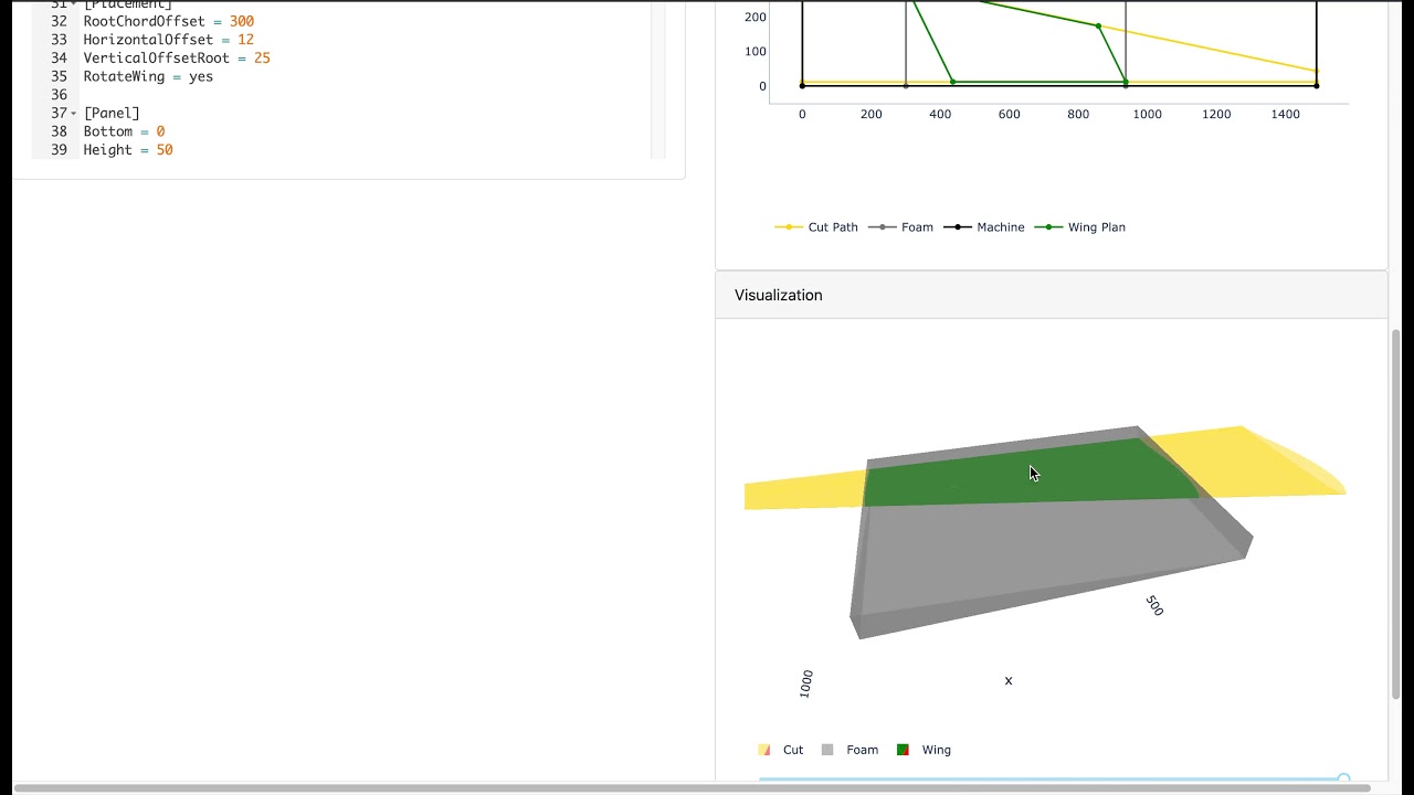
RotateWing = yes
...RootChordOffset - [New] Determines the left/right (z axis in picture below) placement of the panel on the machine. The offset here refers to the distance to the pillar closest to the root chord. So, if the TipChordSide = left, then the distance is between the RootChord and the right-hand pillar.

HorizontalOffset - [New] Min distance between the trailing edge and zero position on the X-axis (in machine picture)
VerticalOffsetRoot - [New] Min distance between the trailing edge and zero position on the Y-axis (in machine picture) for the Root Profile.
For example, in the following profile view, the HorizontalOffset = 20 and the VerticalOffsetRoot = 25

Similarly in plan view, with RootChordOffset=300 and HorizontalOffset=20:

Note that if the HorizontalOffset leads to an infeasible cut (i.e. negative machine axes), the settings will be ignored. This is illustrated below, the yellow lines represents the extremes of the cutting path and already at 0, so any setting of HorizontalOffset below 20 will be ignore:

RotateWing - Rotate the wing so that the leading edge is aligned with the hot wire. Useful for highly swept-back wings. Valid values are "yes" or "no". For example:

...
[Panel]
Bottom = 0
Height = 50
Inset = 0
Depth = 450
SafeHeight = 60
...
Bottom - Placement or offset of the panel above the table (Y-axis in picture)
Height - Thickness or height of the panel
Inset - Placement or offset of the panel away from the edge (X-axis in picture)
Depth - Depth of the panel, i.e. measurement of the panel along the X-axis in the picture
SafeHeight - Height (from 0) the foam wire can safely move above the panel when for instance cutting the trailing edge
...
[Machine]
Width = 1490
Height = 400
Depth = 490
Feedrate = 160
Kerf = 2
Width - Set Width to the width of your foam cutting machine.
Height - Max height - used to check "Out of Bounds" generated gcode
Depth - Max depth - used to check "Out of Bounds" generated gcode
Feedrate - CNC feedrate speed in units / minute.
Kerf - Kerf is the amount of room to offset the hotwire so an accurate amount of foam is cut. Can be an integer or a tuple, in case of a tuple, the first value is the root and the second value the tip kerf. For example, Kerf=2,4 yields the following cut path for the root and tip profiles:

...
[Gcode]
GcodeWireOn = M3 S100
GcodeWireOff = M5
AxisMapping = X,Y,Z,A
ConfigAsComment = yes
InterpolationPoints = 200
...
GcodeWireOn and GcodeWireOff - commands to send before cutting and after cutting is completed to turn the Wire On and Off
AxisMapping - Axis designators to use for the four axis of the CNC machine, the order is left horizontal, left vertical, right horizontal, right vertical
ConfigAsComment - Inserts the config used to generate the gcode as comments in the top of the output gcode file. Valid values are "yes" and "no"
InterpolationPoints - Number of points used to generate the profile - default is 200