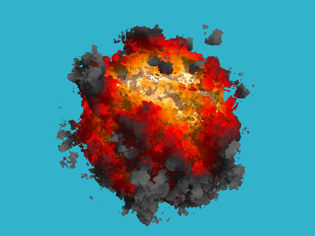
-
Notifications
You must be signed in to change notification settings - Fork 107
KABOOM! in 180 lines of code
This article shows a trivial implementation of a ray marching, the goal is to go a little bit beyond simple spheres I rendered in my raytracer project. I do not aim at getting photorealistic images, I want to have a simple stuff applicable to video games.
As always, we only have a bare compiler at our disposal, no third-party libraries are allowed. I don't want to bother with window managers, mouse/keyboard processing and so on. The result of our program will be a simple picture saved on the disk. I do not pursue speed/optimization at all, my goal is to show the underlying principles.
So, how to draw such a picture in 180 lines of code under such restrictions?

Here is how an animation would look like:

Note that this code is a loose port from a shader available on shadertoy.com. The main idea is to better explain how it works.
Let us split the task into simple steps. As in the raytracing article, to ease the reading flow I adopt the rule 1 step = 1 commit. This way the built-in github diff visualization tool comes extremely handy.
Well, for the step 0 there is no commit. Yup, that's right. The first thing you need to do is to read the previous chapter, which describes the basics of ray tracing. It is very short, in fact, you can skip the reflections and refractions, but I recommend to read at least up to the diffuse lighting stage. The code is quite simple, people even launch it on microcontrollers:

The source code is available here, but it is short, so let's list it:
#define _USE_MATH_DEFINES
#include <cmath>
#include <algorithm>
#include <limits>
#include <iostream>
#include <fstream>
#include <vector>
#include "geometry.h"

const float sphere_radius   = 1.5;

float signed_distance(const Vec3f &p) {
    return p.norm() - sphere_radius;
}

bool sphere_trace(const Vec3f &orig, const Vec3f &dir, Vec3f &pos) {
    pos = orig;
    for (size_t i=0; i<128; i++) {
        float d = signed_distance(pos);
        if (d < 0) return true;
        pos = pos + dir*std::max(d*0.1f, .01f);
    }
    return false;
}

int main() {
    const int   width    = 640;
    const int   height   = 480;
    const float fov      = M_PI/3.;
    std::vector<Vec3f> framebuffer(width*height);

#pragma omp parallel for
    for (size_t j = 0; j<height; j++) { // actual rendering loop
        for (size_t i = 0; i<width; i++) {
            float dir_x =  (i + 0.5) -  width/2.;
            float dir_y = -(j + 0.5) + height/2.;    // this flips the image at the same time
            float dir_z = -height/(2.*tan(fov/2.));
            Vec3f hit;
            if (sphere_trace(Vec3f(0, 0, 3), Vec3f(dir_x, dir_y, dir_z).normalize(), hit)) { // the camera is placed to (0,0,3) and it looks along the -z axis
                framebuffer[i+j*width] = Vec3f(1, 1, 1);
            } else {
                framebuffer[i+j*width] = Vec3f(0.2, 0.7, 0.8); // background color
            }
        }
    }

    std::ofstream ofs("./out.ppm", std::ios::binary); // save the framebuffer to file
    ofs << "P6\n" << width << " " << height << "\n255\n";
    for (size_t i = 0; i < height*width; ++i) {
        for (size_t j = 0; j<3; j++) {
            ofs << (char)(std::max(0, std::min(255, static_cast<int>(255*framebuffer[i][j]))));
        }
    }
    ofs.close();

    return 0;
}
The class of vectors lives in the file geometry.h, I will not describe it here: it is really a trivial manipulation of two and three-dimensional vectors (addition, subtraction, assignment, multiplication by a scalar, scalar product).
So, in main() function I have two loops: the second one simply saves the picture on a disk, and the first loop iterates through all the pixels of the picture, emits a ray from the camera through this pixel, and checks whether this ray intersects with our sphere.
Attention, the main idea of the approach: If in the raytracing article we solved for the intersection of the ray and a sphere analytically, now I compute it numerically. The idea is simple: the sphere has an equation of the form x^2 + y^2 + z^2 - r^2 = 0 ; but the function f(x,y,z) = x^2 + y^2 + y^2 + z^2 - r^2 is defined anywhere in the 3D space. Inside the sphere, the function f(x,y,z) takes negative values, and outside the sphere it is positive. That is, the function f(x,y,z) computes the signed distance to our sphere for each point (x,y,z). Therefore, we will simply slide along the ray until either we get bored or the function f(x,y,z) becomes negative. This is exactly what sphere_trace() does.
Let us implement the simplest diffuse lighting, this is the image I want to get:
The changes are visible in the diff tool.
For the diffuse lighting, in addition to the point of intersection, whe need to know the vector of normal to the surface at this point. I compute this normal vector by simple finite differences on our signed distance function:
Vec3f distance_field_normal(const Vec3f &pos) {
    const float eps = 0.1;
    float d = signed_distance(pos);
    float nx = signed_distance(pos + Vec3f(eps, 0, 0)) - d;
    float ny = signed_distance(pos + Vec3f(0, eps, 0)) - d;
    float nz = signed_distance(pos + Vec3f(0, 0, eps)) - d;
    return Vec3f(nx, ny, nz).normalize();
}
Of course, since we draw a simple sphere, the normal can be obtained much easier, but this approach will serve me later.
Let's draw a pattern on our sphere, for example, this one:
For this rendering I only modified two lines in the code!
How did I draw the image? Of course, I don't have any textures. I just took the function g(x,y,z) = sin(x) * sin(y) * sin(z); it is defined for each point of the 3D space. When my ray crosses the sphere at some point (x,y,z), the value of the function g(x,y,z) sets the pixel color of the sphere.
By the way, note the concentric circles on the sphere - these are the artifacts of my numerical calculation of the intersection.
Why would I want to draw this pattern? In fact, it will help me draw a hedgehog like this:
Where my pattern was black, I want to make a dent on our sphere, and where it was white, on the contrary, I'll do a hump. This trick is known under the name of the displacement mapping. To implement it, it suffices to modify three lines in the source code:
float signed_distance(const Vec3f &p) {
    Vec3f s = Vec3f(p).normalize(sphere_radius);
    float displacement = sin(16*s.x)*sin(16*s.y)*sin(16*s.z)*noise_amplitude;
    return p.norm() - (sphere_radius + displacement);
}
In fact, I re-defined the distance to the surface, I compute it as x^2+y^2+z^2 - r^2 - sin(x)*sin(y)*sin(z). We have just drawn an implicit surface.
Why do I evaluate the product of sines only for the points lying on the sphere? Let us re-define the distance function:float signed_distance(const Vec3f &p) {
float displacement = sin(16*p.x)*sin(16*p.y)*sin(16*p.z)*noise_amplitude;
return p.norm() - (sphere_radius + displacement);
}The difference is very small, it is better visible in the github diff tool. Here is the render:

In such a way we can draw disconnected components!
The previous picture is already starting to resemble an explosion, but the product of sines gives a very regular pattern. I'd like to have some more "torn", more "random" function... We will be helped by the Perlin's noise. Something like this would be much better for our purposes:
How to generate such noise - is out of the scope of this article, but here's the main idea: you need to generate random images with different resolutions, smooth them out to get something like this set:

And then simply sum all of them:

You can find more details here and here.
So let us add a little bit of code, allowing us to generate the noise, and our render transforms magically:

Please notice that we did not modify the actual rendering code! We have only redefined the distance to the surface, i.e. the function that "crumples" the sphere and "tears" it apart.
The only thing I have added in this commit, is the fire colors. Instead of uniform white color I apply colors as a function of the noise amount, check the modifications:Vec3f palette_fire(const float d) {
const Vec3f yellow(1.7, 1.3, 1.0); // note that the color is "hot", i.e. has components >1
const Vec3f orange(1.0, 0.6, 0.0);
const Vec3f red(1.0, 0.0, 0.0);
const Vec3f darkgray(0.2, 0.2, 0.2);
const Vec3f gray(0.4, 0.4, 0.4);
float x = std::max(0.f, std::min(1.f, d));
if (x<.25f)
return lerp(gray, darkgray, x*4.f);
else if (x<.5f)
return lerp(darkgray, red, x*4.f-1.f);
else if (x<.75f)
return lerp(red, orange, x*4.f-2.f);
return lerp(orange, yellow, x*4.f-3.f);
}The colors are defined as a simple linear ramp between five key colors. Here is the final render!
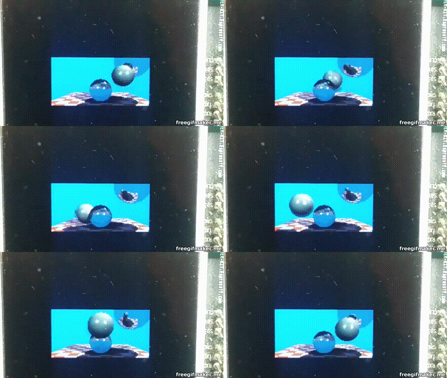
 This raytracing technique is known as the ray marching. The home assignement: take the previous raytracer with blackjack and refractions, and merge it with the KABOOM! Make the KABOOM! illuminate the scene. Add transparency. KABOOM!