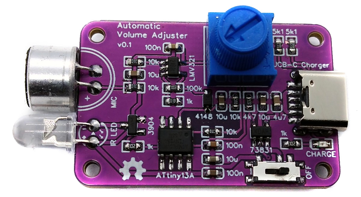
Recently Great Scott built his version of an automatic volume adjuster. In this project he solved one of the biggest problems with modern movies, which is that the conversation volume is way too low in comparison to the music volume. That is why he combined an Arduino microcontroller with a microphone and an IR LED in order to create his automatic volume adjuster. It basically detects when loud movie music starts playing, lowers the volume by sending the respective IR remote control command and then brings the volume back up when the music is over.
Since using an Arduino for this task is a bit of an overkill, here's a version for the ATtiny13A.
- Design Files (EasyEDA): https://easyeda.com/wagiminator/attiny13-automatic-volume-adjuster
- Original Project (YouTube): https://youtu.be/j1V2I-otdzk
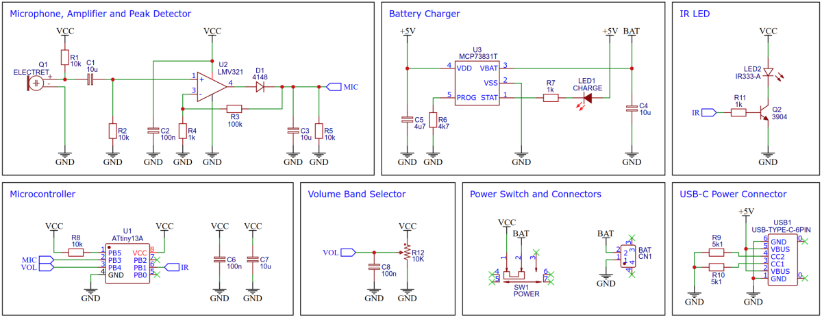
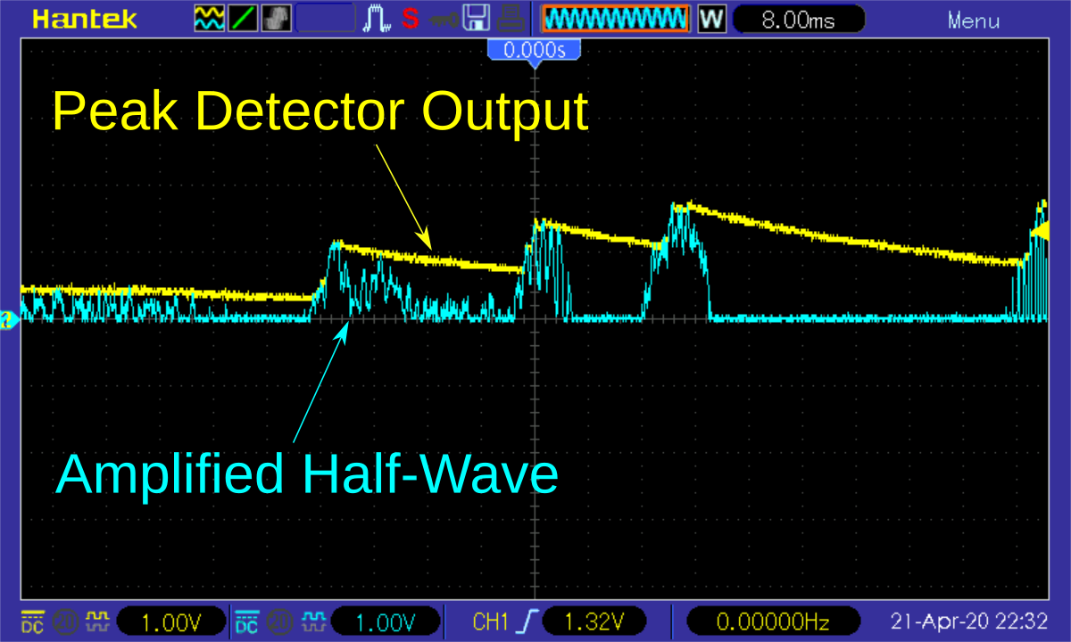
The positive half-wave of the weak audio signal from the electret microphone is first amplified by an inexpensive LMV321 rail-to-rail OpAmp. The following peak detector, consisting of a diode, a capacitor and a resistor, extracts only the maximum values from this signal, i.e. the amplitude or, in other words, the current volume of the audio signal. No more of the audio signal is required and the microcontroller's software is thus relieved. For a more detailed explanation of how the peak detector works, check out David Jones' excellent video.
The IR LED is controlled by a standard BJT transistor. Due to the control with a high-frequency PWM, no series resistor is necessary for the LED.
For battery charging the MCP73831 is used. The MCP73831 is a highly advanced linear charge management controller for use in space-limited, cost-sensitive applications. It employs a constant-current/constant-voltage charge algorithm with selectable preconditioning and charge termination. The constant current value is set with one external resistor (R6). Charging is done via the built-in USB-C connector.
The current volume received by the microphone is measured approximately every 32ms via the analog-to-digital converter (ADC) and averaged with the last values via a simple software-based low-pass filter in order to ignore short peaks. The mean value obtained in this way is compared with the current maximum volume selected via the potentiometer. If the maximum volume has been exceeded, a "decrease volume" command is sent via the IR LED. If the volume is lower than the maximum value minus a hysteresis, an "increase volume" command is sent. No more "increase volume" commands are sent than there were previously "decrease volume" commands. The main loop of the software is shown below:
  while(1) {
    resetWatchdog();                            // reset watchdog
    sleep_mode();                               // sleep until wake up by watchdog

    peak = ((peak << 5) - peak + readADC(MIC_ADC)) >> 5;  // low pass filter

    if(!(--poti_timer)) {                       // time to update poti?
      poti = readADC(POT_ADC);                  // update volume control pot
      if(poti < HYST) poti = HYST;              // minimum poti value
      poti_timer = 16;                          // reset poti timer
    }

    if(!(--peak_timer)) {                       // time to check volume?
      if(peak > poti) {                         // volume too high?
        VOL_DOWN();                             // send "volume down" via IR
        vol_counter++;                          // increase counter for IR signals
        peak = (peak + readADC(MIC_ADC)) >> 1;  // reset peak value
      }
      else if((vol_counter) && (peak < (poti - HYST))) {  // volume too low?
        VOL_UP();                               // send "volume up" via IR
        vol_counter--;                          // decrease counter for IR signals
        peak = (peak + readADC(MIC_ADC)) >> 1;  // reset peak value
      }
      peak_timer = 8;                           // reset peak timer
    }
}A hysteresis is defined at the beginning of the code so that the volume control does not oscillate. It defines the distance between too loud and too quiet. The higher the value, the less often the volume is adjusted.
#define HYST 16 // hysteresisThe implementation for the NEC, SAMSUNG, SONY and RC-5 protocol is taken from TinyRemote. Refer to this project for a complete explanation.
Before compiling you have to define the IR commands for volume up and down. Different protocols and device addresses can be used. You can find the codes for your TV or other devices on the internet or by using an IR decoder.
#define VOL_UP()    NEC_sendCode(0x04,0x02) // LG TV volume up   (addr 0x04, cmd 0x02)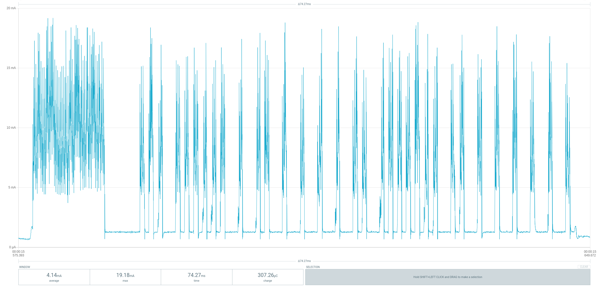
#define VOL_DOWN() NEC_sendCode(0x04,0x03) // LG TV volume down (addr 0x04, cmd 0x03)The code shuts down unused peripherals and utilizes the sleep mode power down function. It is regularly woken up by the watchdog timer. As long as no IR telegram is sent, the device consumes an average current of around 750µA at a battery voltage of 3.7V. The power protocol shown below was created with a Power Profiler Kit II. As you can see, waking up from sleep by the watchdog timer about every 32ms causes current peaks of up to 1.8mA.
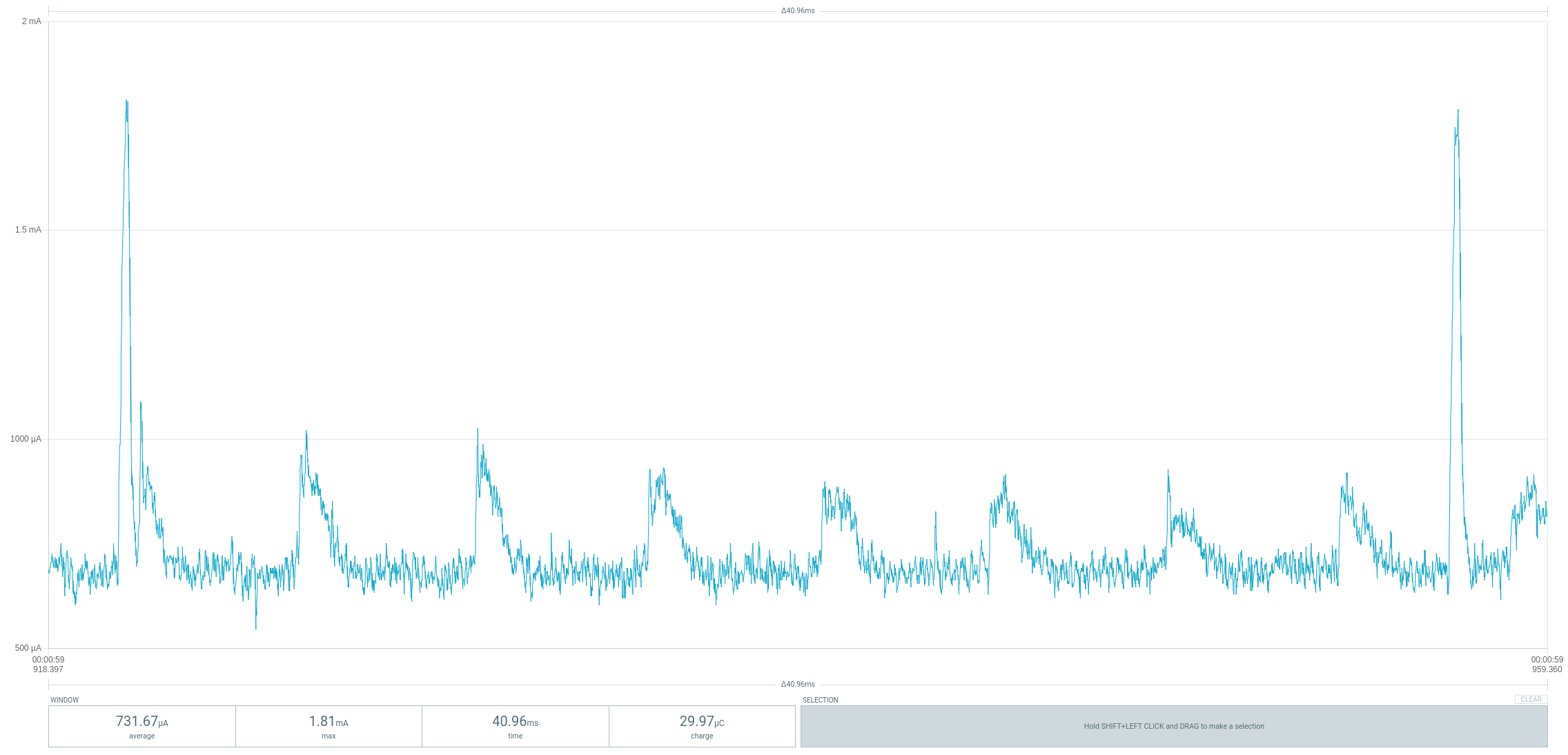
Sending a NEC telegram takes about 70ms and consumes an average of a little over 4mA with current peaks of up to 20mA during this time.
So the bottom line is that even a small 100mAh LiPo battery should have enough capacity for several movie nights. To reduce power consumption even further, the 10kΩ potentiometer can be replaced by a 100kΩ one.
The accuracy of the internal oscillator of the ATtiny13 is +/-10% with the factory calibration. Usually this is sufficient for an infrared remote control. Slight deviations in timing are tolerated by the receiver, since cheap remote controls are usually not more accurate. Nevertheless, it is recommended to manually calibrate the internal oscillator and set the corresponding OSCCAL value at the beginning of the code.
// oscillator calibration value (uncomment and set if necessary)
#define OSCCAL_VAL 0x48Since there is no ICSP header on the board, you have to program the ATtiny either before soldering using an SOP adapter, or after soldering using an EEPROM clip. The AVR Programmer Adapter can help with this. Don't forget to switch off or remove the battery when programming in-circuit!
- Make sure you have installed MicroCore.
- Go to Tools -> Board -> MicroCore and select ATtiny13.
- Go to Tools and choose the following board options:
- Clock: 1.2 MHz internal osc.
- BOD: disabled
- Timing: Micros disabled
- Connect your programmer to your PC and to the ATtiny.
- Go to Tools -> Programmer and select your ISP programmer (e.g. USBasp).
- Go to Tools -> Burn Bootloader to burn the fuses.
- Open the sketch and click Upload.
- Make sure you have installed avrdude.
- Connect your programmer to your PC and to the ATtiny.
- Open a terminal.
- Navigate to the folder with the hex-file.
- Execute the following command (if necessary replace "usbasp" with the programmer you use):
avrdude -c usbasp -p t13 -U lfuse:w:0x2a:m -U hfuse:w:0xff:m -U flash:w:volumeadjuster.hex
- Make sure you have installed avr-gcc toolchain and avrdude.
- Connect your programmer to your PC and to the ATtiny.
- Open a terminal.
- Navigate to the folder with the makefile and the sketch.
- Run
PROGRMR=usbasp make installto compile, burn the fuses and upload the firmware (change PROGRMR accordingly).
- Turn on your television and select your desired volume with the associated remote control. The VolumeAdjuster will not adjust the volume louder than it is now.
- Switch on the VolumeAdjuster and select the maximum volume with the potentiometer. The VolumeAdjuster will reduce the volume of the television as long as the selected maximum volume is exceeded. You can change the maximum volume at any time using the potentiometer.
- Original Project by Great Scott
- ATtiny13A Datasheet
- LMV321 Datasheet
- MCP73831 Datasheet
- TinyRemote
- IR Remote Decoder
- OSC Calibrator
- Audi Peak Detector
- IR remote control explanations by San Bergmans
- Infrared communication concepts (altium.com)
- Peak Detector Explanation (EEVblog)

This work is licensed under Creative Commons Attribution-ShareAlike 3.0 Unported License. (http://creativecommons.org/licenses/by-sa/3.0/)