-
Notifications
You must be signed in to change notification settings - Fork 4
CAN Bus
A Controller Area Network (CAN Bus) is a fault-tolerant communication protocol and electrical standard for connecting microcontrollers and embedded systems. It is similar to more prevalent Ethernet networks but its simplicity and robustness makes it more widely used in industrial control networks. Cars usually contain multiple CAN networks for connecting all of the microcontrollers that make it work.
The robotics team uses CAN bus for communicating with our motor controllers. It allows us to control all of the motors on the robot with just a two-wire interface and greatly reduces the number of wires which need to be run back to the main computer. Additionally, the CAN bus is bi-directional which allows the same bus to send commands and receive feedback from sensors. In the future, we could create our own CAN PCBs for communicating with other devices and sensors on the robot.
If you want to know all of the details of how CAN actually works you can read about it on the Wikipedia page. However, the vast majority of the information available is unnecessary and confusing for how we actually use it. This article will be much more useful because I have diluted it to just the details relevant to our use case. I will also include guidance that is outside of the actual CAN standard.
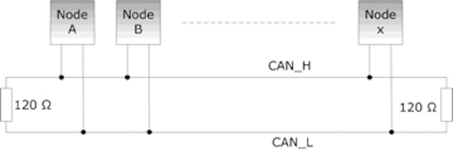
The standard topology of a CAN network is a bus. A standard bus has two long conductors which define the length of the bus. At 1Mb/s, the bus length can be up to 40 meters. Each node is connected to the bus by a stub, which normally has a max length of 1 meter. However, we typically use a daisy-chain topology with no stubs.
Industrial CAN networks will only use a bus topology because it is the most resistant to noise over long distances. However in our use-case with a relatively short bus length, we can use almost any topology without experiencing issues. Star and Ring are possible alternative topologies. In certain robots, it may be infeasible or inconvenient to run a single non-branching bus. It may be more convenient to create a hybrid bus-star topology with a stub that contains more than one device.
A topology may also be chosen to limit the damage if part of the CAN bus becomes disconnected. It would be unwise to have the start of the bus on a moving part of the robot that may accidently become disconnected. Instead, we normally terminate the bus at the end of any moving devices.
Notice in the image above the 120Ω resistors at each end of the bus. These resistors are called the terminating resistors. A CAN bus will not function without at least one terminating resistor. Typically interfacing devices, such as a CAN-to-USB adapter, will contain an optional terminating resistor. Because a network should contain a maximum of two resistors, you usually must manually enable the resistor with a jumper. A robust CAN bus, such as the final robot, must also contain a terminating resistor at the end of the bus. However when doing testing on a bench or with a relatively short bus, the second resistor can be considered optional.
CAN uses differential signaling to reduce interference from noise and avoid other issues. In normal signal wires, the wire is either high or low relative to a common ground. This can cause issues when devices do not share a common ground. Even if devices do share a ground, it might be at a slightly different voltage because of voltage drops across the wires connecting them. Differential signaling eliminates this issue by communicating bits as a difference in voltage between two wires. The two wires are called CAN High and CAN Low because neither wire is actually ground.
The wires selected to carry a CAN bus should always be a twisted-shielded pair. Twisting of wires ensures that if electrical noise induces a voltage in one wire, an equal and opposite voltage will be induced in the other wire. Because of differential signaling the resulting differential voltage will be unaffected by noise. Shielding additionally protects wires from induced voltages. For maximum effectiveness, the shielding should be electrically connected to ground, but it is usually not necessary for our use-case.
Unlike Ethernet, computers do not usually come with a CAN bus interface, and connecting our laptops or Raspberry Pi's to a CAN network requires a specialized adapter. Here is a list of some possible adapters:
The CANable is our preferred adapter because it's USB interface allows it work with all of our boards and computers. Make sure you see the documentation on how to configure the terminating resistor and program the firmware.
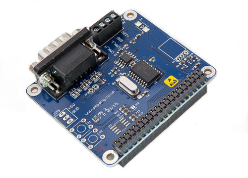
Copperhill makes a variety of CAN hats for Raspberry Pi. Some of them include a voltage regulator (SMPS) to also power the Raspberry Pi off of a battery.
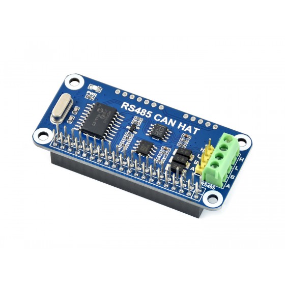
We have not used this CAN Hat but, it looks like a promising low-cost option.
The Hero Board is the most reliable way of upgrading the firmware on our CTRE motor controllers.
In Linux the SocketCAN driver is responsible for enabling communication with CAN devices. You can install SocketCAN its related utilities with sudo apt install can-utils. See the SocketCAN documentation for issues related to CAN in Linux.
If you have SocketCAN installed, when you connect a CAN adapter you should immediately see the device along with other network devices in ifconfig or ip a. In these utilities you will see it initially listed as DOWN. Before you can use the interface, you need to configure the link speed and then tell Linux to enable it. For more information see Bringing CAN interface up or the CANable documentation.
 $ sudo ip link set can0 type can bitrate 1000000 # Set link speed to 1Mb/s
 $ sudo ip link set up can0
Unless you configure Linux, you will need to manually enable the interface after each restart. See this for possible ideas and update this documentation if it works.
The can-utils package includes all kinds of useful commands. See here for a full list.
- canbusload : calculate and display the CAN busload
- Home
- Programming
-
Electrical
- Component Guide
- Single Board Computers
- Design
- Machine Learning/Intelligence
- Systems Engineering


