-
Notifications
You must be signed in to change notification settings - Fork 44
Platforms
HELIOS++ supports static and dynamic as well as terrestrial and airborne platforms. All platforms are defined in data/platforms.xml. For an overview of all possible tags and parameters in this XML, go to XML Tag and Parameter Summary at the bottom of the page.
The platform is assigned in the <survey> tag of the survey.xml together with the survey name, the scene, the scanner and optionally a seed. Referencing the different components is done by specifying the absolute or relative path of the XML file, followed by a hash (#) and the ID of the entry.
<survey name="toyblocks_als"
        platform="data/platforms.xml#sr22"
        scanner="data/scanners_als.xml#riegl_vq-880g"
        scene="data/scenes/toyblocks/toyblocks_scene.xml#toyblocks_scene">
For each scan position or way point, a <leg> is defined in the survey.xml. Within this tag, platform position is provided using the tag <platformSettings>.
Terrestrial laser scanning (TLS) simulations are conducted from the static platform tripod. Per default, it is mounted at a height of 1.5 m. Each leg is considered a single scan position. Defining the horizontal and vertical field of view is explained at Scanner Settings.
There are three types of platforms available.
-
linearpath: This platform type simply moves on a straight line from one waypoint (
leg) to the next with constant speed (no speed-ups or slow-downs). -
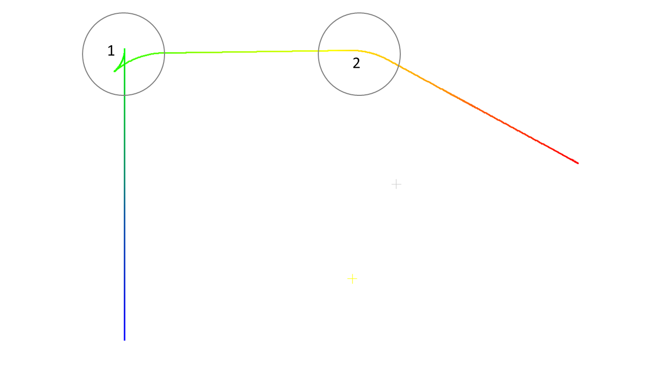
groundvehicle: This platform type performs different turns at the waypoints depending on the curve angles. For sharp turns with turn angles larger than 36°, the vehicle performs a two-point turn (1). For wide angle-turns, it performs a curved turn (2).
 Figure: Trajectory output for a groundvehicle survey, coloured by GpsTime.
IMPORTANT NOTE: There are several bugs with the multicopter platform, like legs not ending when using slowdownEnabled (#22, #37) or the user-defined speed (movePerSec_m) not being used. We advise to use the linearpath platform instead. In the platforms.xml, this could look like that:
	<platform id="copter_linearpath" name="Quadrocopter UAV" type="linearpath">
		<scannerMount x="0" y="0" z="0.2">
			<rot axis="x" angle_deg="180" />
			<rot axis="z" angle_deg="175" />
		</scannerMount>
	</platform>
This platform would be compatible with e.g., the riegl_vux-1uav. Using the rotations in the scannerMount, the copter pitch during forward movement is simulated.
-
multicopter:
This platform type simulates the behaviour of a multicopter by tilting into the movement direction and tilting backwards for slow-down. By default, the copter approaches the waypoint in a straight line, stops both movement and scanning, turns towards the next waypoint and then accelerates and starts scanning again (
stopAndTurn). If the parametersmoothTurnis set to "true" instead, the copter turns smoothly at the waypoints while moving and scanning (so-called bank turns). Optionally,yawAtDeparturecan be set explicitly if the copter is supposed to face in another direction than the next waypoint.
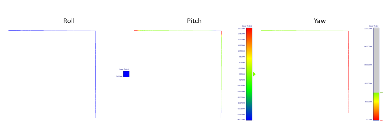
Figure: Trajectory output for a multicopter survey instopAndTurnmode, colored by the aircraft principal axis. The flight starts on the bottom right and ends at the top left.

Figure: Trajectory output for a multicopter survey insmoothTurnmode, colored by the aircraft principal axis. The flight starts on the bottom right and ends at the top left.
The multicopter has multiple parameters to control slowdown and speedup as well as roll and pitch angles. For an overview, go to XML Tag and Parameter Summary.
Mobile laser scanning (MLS) is simulated using a dynamic terrestrial platform, such as a car or tractor. Two tractor and two car platforms are currently implemented with different scanner mounts using either the linearpath or the groundvehicle platform type.
Note that for terrestrial (static or dynamic) surveys, the onGround parameter comes in handy which is set in the <platformSettings> tag in the survey.xml. It forces the platform to be placed at the lowest scene point (i.e. the ground) and any specified z-value will be ignored.
For dynamic simulations, at least two legs have to be defined, corresponding to the start and stop way point, and the moveperSec_m parameter controls the speed of the platform moving between the waypoints.
Airborne laser scanning (ALS) simulations are performed from an airplane (with platform type linearpath) or multicopter. Currently, one aircraft for conventional ALS surveys and a quadcopter for UAV-borne surveys are implemented.
Users can extend the platform.xml with custom platforms. For this, the id, name, and type have to be specified. Optionally, a value for the drag may be given.
<platform id="quadcopter" name="Quadrocopter UAV" type="multicopter" drag="0.01">How the scanner is mounted relative to the platform is defined in the scannerMount-tag. For example, the following XML snippet creates a tripod platform with the scanner mounted at 2 m (the height of the default tripod is 1.5 m):
<platform id="tripod_2m" name="TLS Tripod (2 m)" type="static" drag="0">
	<scannerMount x="0" y="0" z="2.0">
	</scannerMount>
</platform>Additionally, rotations can be defined, for instance to specify that the scanner is facing down and scanning orthogonally to the platform orientation (as is the case for ALS):
<platform id="sr22" name="Cirrus SR-22" type="linearpath">
    <scannerMount z="0.7" rotation="global">
        <rot axis="Z" angle_deg="-90" /> <!-- scan plane: left-to-right -->
        <rot axis="Y" angle_deg="90" /> <!-- main direction: downwards -->
    </scannerMount>
</platform>
The scanner's coordinate system is defined as R-F-U, i.e. the first axis (X) is pointing to the right wingtip, the second axis (Y) is pointing towards the front of the platform and the third axis (Z) is pointing upwards, i.e. to zenith. For rotating mirror, fibre array and oscillating scanners, the scan plane is created by the second and the third axis, and the main scan direction is the Y-Axis (forward). Without rotation, this results in a scan pattern normal to the horizon:

Note that there are two modes of rotation, as defined in the scannerMount-Tag: rotations="global", where the axes of rotation are kept fixed in space, and rotations="local", where the axes are rotated with the scanner. The difference is prominent when completing turns about multiple axes, and is shown in the following example. If no mode is provided, global mode assumed.
The task here is to create a scanner that looks backwards, 20° off-nadir.
| Rotations | Global mode | Local mode |
|---|---|---|
| None |  |
 |
| Y-axis: 90° |  |
 |
| Y-axis: 90°, X-axis: -110° |  |
 |
| Y-axis: 90°, Z-axis: -110° |  |
 |
The orange triangle shows the scan plane. Note, how the axes in the local mode change their direction with respect to the platform after every rotation. For the global mode, the following definition gives the desired result:
<scannerMount x="0.0" y="0.0" z="0.0" rotations="global">
    <rot axis="y" angle_deg="90" />
    <rot axis="x" angle_deg="-110" />
</scannerMount>
and for the local mode, this definition is correct:
<scannerMount x="0.0" y="0.0" z="0.0" rotations="local">
    <rot axis="y" angle_deg="90" />
    <rot axis="z" angle_deg="-110" />
</scannerMount>
Note that an additional rotation is applied in the scanner's beamOrigin tag, which uses the same syntax. We suggest to use the beamOrigin rotation to point the scanner downwards and scan left-to-right (as this is the most common usecase) and the scannerMount (which is applied thereafter) for specialized mounts such as 23° off-nadir for airborne bathymetry (although this is usually solved by using a conical scan pattern with an opening angle of 46°).
| Attribute | Default value | Comment |
|---|---|---|
id |
REQUIRED | |
name |
||
type |
"static" | possible values: "multicopter", "linearpath", "groundvehicle"; any other entries will use the default static platform |
drag |
||
engine_max_force |
0.1 | specific to multicopter |
speedup_magnitude |
2.0 | specific to multicopter |
slowdown_magnitude |
2.0 | specific to multicopter |
slowdown_distance |
5.0 | specific to multicopter |
base_pitch_deg |
-5.0 | specific to multicopter |
roll_speed_deg |
28.65 | specific to multicopter |
pitch_speed_deg |
85.94 | specific to multicopter |
yaw_speed_deg |
85.94 | specific to multicopter |
roll_offset_deg |
25.0 | specific to multicopter |
pitch_offset_deg |
35.0 | specific to multicopter |
| Attribute | Default value | Comment |
|---|---|---|
x |
0 | |
y |
0 | |
z |
0 | |
rotations |
"global" | possible values: "global", "local" |
| Attribute | Default value | Comment |
|---|---|---|
angle_deg |
||
axis |
possible values: "x", "y", "z" (upper or lower case) |
<positionXNoise [...]><positionYNoise [...]><positionZNoise [...]><attitudeXNoise [...]><attitudeYNoise [...]><attitudeZNoise [...]>
| Attribute | Default value | Comment |
|---|---|---|
type |
"NORMAL" | possible values: "NORMAL", "UNIFORM" |
mean |
0.0 | specific to NORMAL distribution |
stdev |
1.0 | specific to NORMAL distribution |
min |
0.0 | specific to UNIFORM distribution |
max |
1.0 | specific to UNIFORM distribution |
clipEnabled |
"false" | |
clipMin |
0.0 | |
clipMax |
1.0 | |
fixedLifespan |
1 | see Error sources and randomness control |
Airplane model CC-BY Emmanuel Baranger