client scanning and decoding
Wiki ▸ Scanning and Decoding
The client has the capability to decode 2D Data Matrix barcodes located on specimen tubes. The barcodes on many tubes can be decoded at once when they are placed in a microwell plate. Images of microwell plates captured using a camera or flatbed scanner can be decoded by the client.
Before a flatbed scanner can be used with the client, configuration is required. Please see the following link for the instructions:
In the client, decoding of microwell plate images is possible in the following scenarios:
-
When linking specimens to patients: accessed by selecting Processing -> Specimen Link from the main menu when in the processing view (to change to this view select View -> Open Processing View).
-
When assigning storage locations to specimens: accessed by selecting Processing -> Specimen Assign from the main menu when in the processing view.
-
When creating dispatches : accessed by selecting Processing -> Add Dispatch from the main menu when in the processing view.
-
When processing received dispatches : accessed by selecting a Receiving dispatch from the Specimen Transit tab in the processing view.
-
When testing image decoding: accessed by selecting Scanning and Decoding -> Decode Image from the main menu.
Decoding a microwell plate is done using the Decode Image Dialog which is shown in the figure shown below.
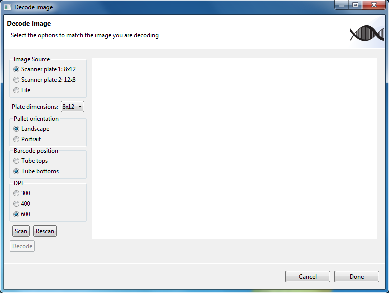
In the figure shown above, two regions on the flatbed scanner have been configured: one is named 8x12 and the other 12x8.
The dialog allows the user to select different settings on the left hand side, and displays an image on the right. The settings are select as follows:
| Setting | Description |
|---|---|
| Image Source | Where the image will be acquired or loaded from. Possible selections here are: one for each region defined with flatbed scanner configuration or and image on the file system (hard disk or network location). |
| Plate dimensions | The dimensions of the microwell plate. Valid selections are: 8x12 (eight rows by 12 columns), 10x10, 12x12, and 9x9. |
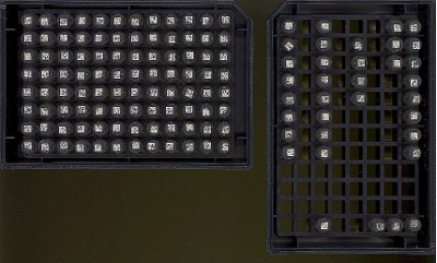
| Pallet orientation | The orientation of the microwell plate: either landscape or portrait. Landscape mode means that the row count (horizontal) is less than the column count (vertical). The figure below shows two plates, the one on the left is in landscape orientation and the one on the right is in portrait orientation. Note that if a plate is in portrait orientation, 8x12 should be selected as the dimensions. |
| Barcode position | Where on the tubes the 2D barcodes are located. Usually, the 2D barcodes are on the bottom of the tubes. However, sometimes, some images may have them on the tops of the tubes. |
| DPI | When the image source is a flatbed scanner, this setting will be displayed, and allows the user to change the DPI (dots per inch) the image will be scanned at. This setting is not displayed if the image source is a file on the file system. |
Each tube has a position label that identifies the position of a single tube in the microwell plate. A row uses an upper case letter starting at A, and a column uses a number starting at 1. The fist tube has A1 as a position label. On a 96 well micro plate the last tube has H12 as a position label.
It is important that the orientation and barcode position settings are correct since it is used by the software to determine where the first cell, A1, is located.
Once the image source and the settings are selected, you can press the Scan button to acquire an image with the flatbed scanner. Acquiring an image will take a few seconds to complete.
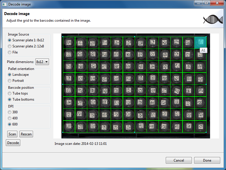
The scanned image is now displayed in the dialog box as shown in the figure above. Superimposed on the image, is a grid with the number of cells that corresponds to the dimensions selected in Plate dimensions. Each cell of the grid represents a well in the plate. The well may or may not have a tube present in it. If a tube is present in the well it will be decoded. If a tube is not present then nothing will be decoded. It is important that each cell contains the entire barcode so that the barcode is decoded properly.
The user can use the mouse and keyboard to adjust the size of the grid. See section Keyboard and mouse actions for instructions on how to manipulate the grid and the scanned image.
The highlighted cell, shown in cyan, is a visual cue for the position of the first cell. Hovering with the mouse over a cell displays the position label for that cell.
Below the scanned image, the time and date the scan happened at is displayed.
Once the cells are aligned correctly the user can press the Decode button to decode the contents of each barcode. Decoding the barcodes will take a few seconds. The figure shown below shows the dialog box after decoding has completed.
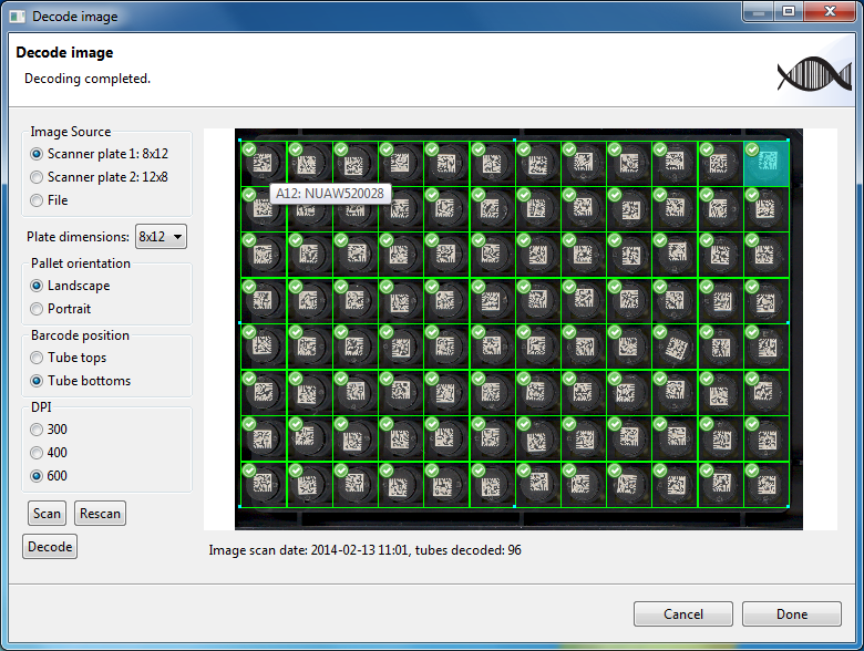
Due to ice build up or dust on the flatbed scanner it is possible that some of the barcodes are not decoded. Each cell that was correctly decoded has a green check box displayed in the top left. The text below the image is updated to state the total number of tubes decoded. Hovering over a cell now displays the position label along with the text contained on the barcode.
If a cell was not decoded the following options are available:
-
Press the Scan button and then the Decode button to start from scratch. This may be done if the scanned image is obscured by dirt or ice buildup on the tubes. In this case the history of what was decoded is lost.
-
Press the Rescan button and then the Decode button. This will aggregate the new decoded information with the previous information.
-
Resize the grid and press the Decode button. Sometimes, missed cells may now be decoded.
-
Change the DPI setting, press the Rescan button and then the Decode button. This will also aggregate the new decoded information with the previous information.
-
Use a hand held scanner to decode the missed cells. This can only be done after accepting the current decode results and pressing the Done button.
Once you are happy with the results of the decoding (you may still have missed cells) you can press the Done button.
As an additional example, the following figure shows the decoded tubes from a scanning region configured as portrait:
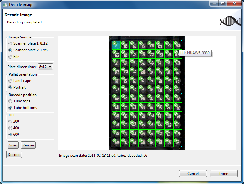
Tube A1 is at the top left and tube H1 is at the top right (as shown by where the mouse is hovering).
Decoding an image already on you file system is very similar to using a flatbed scanner. There are less settings when doing this and are shown in the image below.
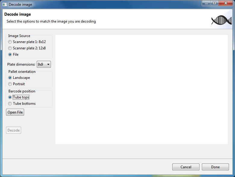
Note that the DPI setting is no longer shown and the Scan and Rescan buttons are replaced with the Open File button.
Pressing the Open File button allows you to select a file from the file system. On Microsoft Windows 7 the dialog looks as follows:
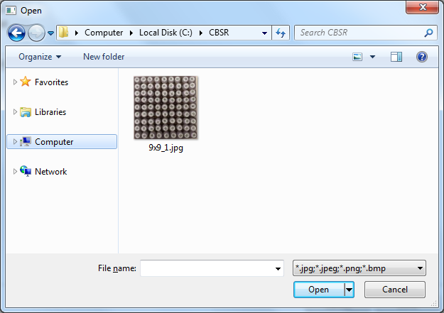
With this dialog you can open files with extensions: jpg, jpeg,
png and bmp. After selecting a file, it displayed in the dialog
box and can then be decoded. The following figure shows an image of a
decoded 9x9 plate.
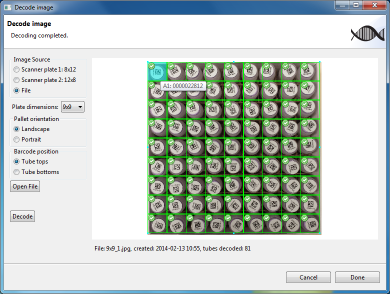
Note that in this image the barcodes are present on the tops of the tubes and the setting selected for Barcode positions is Tube Tops. Cell A1 is at the top left.
Here is a list of keyboard keys that can be used to manipulate the image and the grid.
| Key(s) | Description |
|---|---|
| Direction keys: up, down, left, right | Moves the grid in the corresponding direction by one pixel. Hold down to repeat. |
Here is a list of mouse actions that can be used to manipulate the image and the grid.
| Action | Description |
|---|---|
| Left click and drag, outside grid | Scrolls the image. |
| Left click and drag, inside grid | Moves the grid. |
| Left click on resize handle and drag | Resizes the entire grid. Note that there are eight resize handles on the region, one on each corner, and one on each edge midpoint. |
Hold Ctrl key and move mouse wheel. |
Zooms into or out of the image. |