client scanning and decoding configuration
Wiki ▸ Scanning and Decoding ▸ Configuration
From the client main menu, select Configuration -> Preferences to open the Preferences dialog box. Select and expand the Scanning and Decoding item on the left hand side and you will see a dialog box similar to the one shown below. Note that you do not have to be logged into the Biobank server to perform these steps.
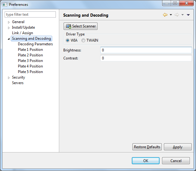
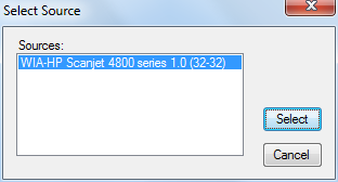
To select a flatbed scanner, press the Select Scanner button. The figure shown below shows the
dialog box that is shown when the button is pressed.
Once a scanner is selected, the selection for Driver Type will automatically update, but sometimes the the correct type is not selected. Use the check boxes here to override the automatic selection if it was incorrect. For best results, always use the WIA driver type.
The values in Brightness and Contrast allow these setting to be adjusted when an image is scanned. However, these parameters do not work on Hewlett-Packard scanners when using the WIA based driver, so these values can be left at zero.
The values for these parameters do not need to be modified by normal users, and they can be left at their default values. If there is a problem with scanning or decoding you may be instructed to change some of these values during technical assistance.
Select Decoding Parameters from the Preferences dialog box (note that the Scanning and Decoding item needs to be expanded). The dialog now looks similar to the one shown below:
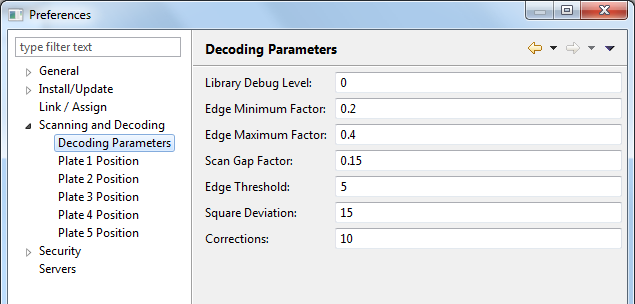
Each setting is described below:
| Setting | Description |
|---|---|
| Library Debug Level | Used to output debugging information when scanning and decoding images. Possible values are 0 through 9. The higher the value the more detailed the debugging information. A zero values does not generate any output. |
| Edge Minimum Factor | Pixel length of smallest expected edge in image as a factor of the cell width or cell height (whichever is bigger). The default values is 0.2. |
| Edge Maximum Factor | Pixel length of largest expected edge in image as a factor of the cell width or cell height (whichever is bigger). The default values is 0.4. |
| Scan Gap Factor | The scan grid gap size as a factor of the cell width or cell height (whichever is bigger). The default value is 0.15. |
| Edge Threshold | Set the minimum edge threshold as a percentage of maximum. For example, an edge between a pure white and pure black pixel would have an intensity of 100. Edges with intensities below the indicated threshold will be ignored by the decoding process. Lowering the threshold will increase the amount of work to be done, but may be necessary for low contrast or blurry images. The default and recommended value is 5. |
| Square Deviation |
Maximum deviation (in degrees) from squareness between adjacent barcode sides. The default and
recommended value is N=15 and is meant for scanned images. Barcode regions found
with corners <(90-N) or >(90+N) will be ignored by the
decoder. The default value is 15.
|
| Corrections | The number of corrections to make while decoding. The default and recommended value is 10. |
Plate positions can be configured to decode different sized well plates. For example, the first plate can be configured to scan 96 well plates, the second for 81 well boxes, etc. Plate regions configure which are on the flatbed scanner will be scanned when processing specimens.
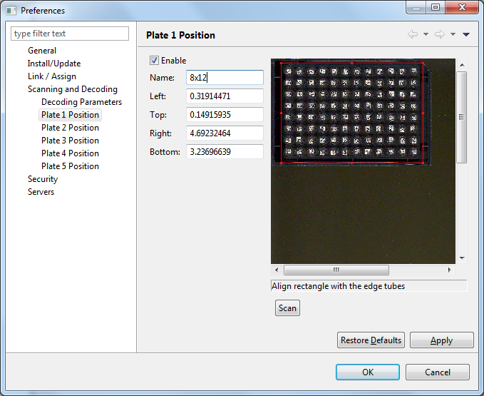
Select Plate 1 Position from the Preferences dialog box (note that the Scanning and Decoding item needs to be expanded). The dialog now looks similar to the one shown below:
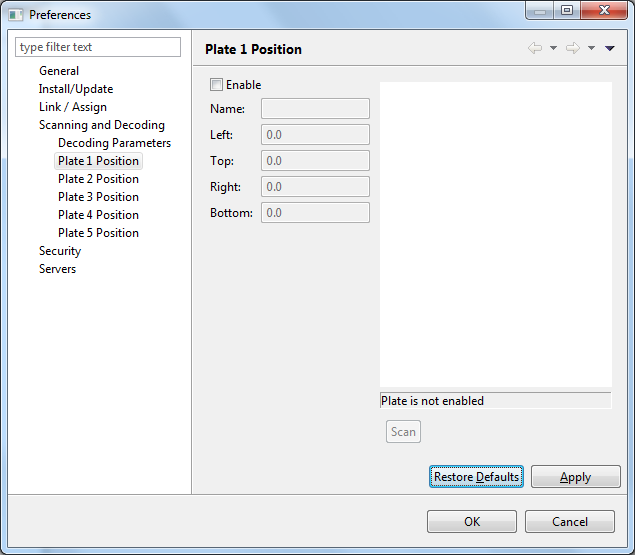
To define a plate region do the following after selecting a scanner as described above:
-
Place a pallet that contains tubes on the flatbed scanner. Ensure the top edge of the pallet is touching the top of the scanning region, and the right edge of the pallet is touching the right margin.
-
Select the plate position you are going to define. If it is the first select Plate 1 Position.
-
Click on the Enable check box.
-
Press the Scan button. Now wait for the scanner to scan the entire flatbed.
-
Once the scan is done, you will see something similar to the figure shown above. The figure shows the scanned image after zooming in, and superimposed is a region shown in red. The region in red will be scanned when decoding a plate during specimen processing.
-
You can adjust the size of the region using the mouse. If the region is moved, the numbers displayed for Left, Top, Right, and Bottom change. You can also enter numbers into these values to change the position of the corresponding edge of the region.
If you move the mouse to one of the corners, or the midpoint of one of the edges, you can resize the grid by left clicking on the mouse and moving it. The whole grid can be moved by pressing the left mouse button while hovering inside the region. See section Keyboard and mouse actions for instructions on how to manipulate the region and the scanned image.
-
Once the region contains all the tubes press the Apply button. It is usually better to make the region slightly larger than the edge of the tubes so as to not cut off the barcodes.
-
Repeat from step 2 to define any more pallet scanning regions.
Usually only one pallet scanning region is required for normal operation of the software.
The figure below shows an example of how Plate 2 can be defined. Here Plate 2 is scanned in Portrait mode and is touching the top and the left margin of the of the flatbed region.
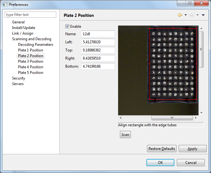
You can assign a name to each plate region so that it is easier to remember it later when processing specimens. In the sample configuration described above, plate 1 was given the name 8x12 and plate 2 12x8. By using different names it makes it easier to use different plate configurations during specimen processing.
To test if your configuration yields valid decoded tubes, use Scanning and Decoding -> Decode Image from the main menu.
Here is a list of keyboard keys that can be used to manipulate the image and the region.
| Key(s) | Description |
|---|---|
| Direction keys: up, down, left, right | Moves the scan region in the corresponding direction by one pixel. Hold down to repeat. |
Here is a list of mouse actions that can be used to manipulate the image and the region.
| Action | Description |
|---|---|
| Left click and drag, outside region | Scrolls the image. |
| Left click and drag, inside region | Moves the region. |
| Left click on resize handle and drag | Resizes the region. Note that there are eight resize handles on the region, one on each corner, and one on each edge midpoint. |
Hold Ctrl key and move mouse wheel. |
Zooms into or out of the image. |